digitalWrite(buzzerPin, LOW); // turn the alarm on
Depending on the type of "buzzer", you may have to drive it with the tone library say at 4 KHz.
digitalWrite(buzzerPin, LOW); // turn the alarm on
Depending on the type of "buzzer", you may have to drive it with the tone library say at 4 KHz.
I will try that when I get home. I did however try an LED as well as my voltmeter. No output was recorded.
Sketch works perfectly here, so don't change it if things don't work.
It's up to your hardware now.
Use an active buzzer that works with a DC voltage.
Looks like this.
Connect between pin10 and ground (watch polarity).
The brightness of the activity LED (PWM pin9 and ground with ~220ohm resistor) now depends on knock strength.
The light output is different. It expects a (single) 5volt relay module with opto LED between +5volt and pin 11.
You can test it with a LED/resistor between +5volt and pin11.
Button goes from pin12 to ground.
It turns off the light, and now also instantly silences the buzzer (new code, so re-upload).
Leo..
I didn't have a relay installed while testing. do you think the board was looking for the coil resistance and that's why the alarm wouldn't sound? as mentioned, I didn't have any voltage on pin 10.
let me play around a bit more and see what i come up with.
Can I use a LED in place of the buzzer for now?
you mentioned new code.. did you update your previous post?
Note that pins have changed because PWM is now used for the activity LED.
I have commented almost everything, so read carefully.
Code part for the light is written for a common/ebay single relay module with opto coupler.
Pin11 is set default HIGH for that (= relay off) in void setup().
And made LOW to turn the light (relay) on.
If you want to use a normal relay with diode/transistor/base resistor, then the code has to be changed.
An Arduino pin can't drive a relay directly!
Let me know, so I can advise.
This is how I thought an alarm would be needed:
The "eventCounter" value is increased by one every time the knock threshold is reached.
The counter is also decreased by one every second.
You could say fast attack and slow decay.
The alarm is activated when a set threshold of the eventCounter is reached.
I have added two lines near the end of the code, so the buzzer turns instantly off when you kill the lights with the button. Nothing to do with normal functioning. Just polishing the code.
Love to see some pictures.
Leo..
first off, thank you very much for your help! this means alot to our family. I hope this come back to you ten fold!
My goody box is pretty bare at this time. I will need to order and restock the most basic items. As for the relay, I typically use a diode/transistor setup do to cost and space for most builds with UNO. I am located in the middle of nowhere , the only electronic supply near me is 55 minutes away and its a radio shack. This means I order most of my stuff online and wait...lol
if its all the same to you, I will use a standard relay with transistor.
I was also thinking, maybe it would be better to use a pot to adjust the sensitivity. This would allow for on the fly tailoring if conditions change. What are your thoughts on this? the trick will be getting the setting just right. If its to sensitive the we will get a false alarm. But if its not sensitive enough, a seizure may go undetected. The only way this can be adjusted is in real time as he is sleeping normal. I would set it so it was very sensitive and keep adjusting over time until a normal sleep pattern and threshold is found.
thanks again!
New code for normal DIY relay driver attached.
I think it's wise to test the code first before deciding to add another control.
See which variable is the problem. Threshold or eventCounter.
I tried to output everything to serial monitor, so easy to see.
If you put things in a box, it might be wise to add a 10k lineair (10kB) pot to the front panel.
Then you can always connect it to e.g. A1, and code for it if needed.
Hope your son is ok.
Leo..
// knock sensor/alarm
// Piezo, with 1Megohm load resistor across, connected to A0 and ground
// 5volt buzzer on pin 10

const int alarmThreshold = 100; // alarm threshold from 1 (very sensitive) to 1022
const int alarmDuration = 10000; // alarm duration in milliseconds
const byte eventThreshold = 50; // number of events before alarm | 1-255

byte piezoPin = A0;
byte ledPin = 9; // external LED
byte buzzerPin = 10; // alarm buzzer
byte lightPin = 11; // room light relay module
byte buttonPin = 12; // button to turn the light off
// timed events
unsigned long currentMillis;
unsigned long previousMillis;
unsigned long currentAlarm;
unsigned long interval = 1000;
int rawValue; // raw A/D readings
int piezoValue; // peak value
byte ledValue = 0; // brightness
byte eventCounter = 0; // knock events over the threshold
boolean ledState;
boolean alarmState;
boolean alarmLockout;
boolean lightState;

void setup() {
  analogReference(INTERNAL); // remove this line if too sensitive
  Serial.begin(115200); // serial monitor for raw piezo output
  pinMode(ledPin, OUTPUT); // pin 9
  pinMode(buzzerPin, OUTPUT); // pin 10
  pinMode(lightPin, OUTPUT); // on pin 11
  pinMode(buttonPin, INPUT_PULLUP); // light off button from pin 12 to ground
  Serial.println(F("Knock Sensor"));
  Serial.println(F("============"));
}

void loop() {
  currentMillis = millis(); // update every loop
  piezoValue = 0; // reset before measuring
  // events countdown to zero
  if (currentMillis - previousMillis >= interval) {
    if (eventCounter > 0) {
      eventCounter --;
      Serial.print(F("Event counter is "));
      Serial.println(eventCounter);
    }
    previousMillis = currentMillis;
  }
  // read sensor
  for (int x = 0; x < 250; x++) { // multiple A/D readings
    rawValue = analogRead(piezoPin);
    if (rawValue > piezoValue) {
      piezoValue = rawValue; // store peaks
    }
  }
  // action
  if (piezoValue == 0 && ledState) { // if no movement and LED is on
    analogWrite(ledPin, 0); // turn LED off
    ledState = LOW; // remember LED is now off
  }
  if (piezoValue > 0) { // if there is any movement
    Serial.print(F("Piezo value is "));
    Serial.println(piezoValue); // print the value
    ledValue = map(piezoValue, 0, 1023, 0, 255); // map to PWM range
    analogWrite(ledPin, ledValue); // LED brightness depends on knock intensity
    if (!ledState) {
      ledState = HIGH; // remember LED is now on
    }
  }
  if (piezoValue > alarmThreshold) { // if movement is over the threshold
    Serial.print(F("Knock was over the threshold of "));
    Serial.println(alarmThreshold); // prints threshold
    if (eventCounter < eventThreshold) { // add event to the event counter | with limit
      eventCounter ++;
    }
    Serial.print(F("Event counter is "));
    Serial.println(eventCounter);
  }
  if (eventCounter >= eventThreshold) { // if event count reaches the threshold
    if (!alarmState && !alarmLockout) { // turn alarm on | once
      digitalWrite(buzzerPin, HIGH); // turn the alarm on
      alarmState = HIGH; // remember it
      currentAlarm = currentMillis;
      Serial.println(F(">>>> ALARM ON <<<<"));
    }
    if (!lightState) {  // if light is off
      digitalWrite(lightPin, HIGH); // light relay on
      lightState = HIGH; // remember light is on
      Serial.println(F(">>>> LIGHTS ON <<<<"));
    }
  }
  if (alarmState && currentMillis >= currentAlarm + alarmDuration) { // alarm duration
    digitalWrite(buzzerPin, LOW); // turn the alarm on
    alarmState = LOW; // remember it
    alarmLockout = HIGH; // not re-triggering
  }

  if (digitalRead(buttonPin) == LOW && lightState) { // if lightoff button is pushed and the light was on
    digitalWrite(lightPin, LOW); // light relay off
    lightState = LOW; // remember it
    digitalWrite(buzzerPin, LOW); // turn the alarm off if it's still on
    alarmState = LOW; // remember it
    alarmLockout = LOW; // alarm is possible again
    eventCounter = 0;
  }
}
I just tried to install the new code.
Arduino: 1.6.10 (Windows 8.1), Board: "Arduino/Genuino Uno"
C:\Users\rodger\AppData\Local\Temp\untitled2119808780.tmp\sketch_jul26b\sketch_jul26b.ino: In function 'void loop()':
sketch_jul26b:64: error: 'alarmThreshold' was not declared in this scope
if (piezoValue > alarmThreshold) { // if movement is over the threshold
^
sketch_jul26b:67: error: 'eventThreshold' was not declared in this scope
if (eventCounter < eventThreshold) { // add event to the event counter | with limit
^
sketch_jul26b:73: error: 'eventThreshold' was not declared in this scope
if (eventCounter >= eventThreshold) { // if event count reaches the threshold
^
sketch_jul26b:86: error: 'alarmDuration' was not declared in this scope
if (alarmState && currentMillis >= currentAlarm + alarmDuration) { // alarm duration
^
sketch_jul26b:100: error: expected '}' at end of input
}
^
sketch_jul26b:100: error: expected '}' at end of input
exit status 1
'alarmThreshold' was not declared in this scope
This report would have more information with
"Show verbose output during compilation"
option enabled in File -> Preferences.
Seems that you haven't copy/pasted the whole sketch.
The top lines are missing?
Use the [Select] button on top of the code window, and then copy the text.
Coppied sketch compiles and runs here without a problem.
Leo..
I see the mistake. Thanks!
Hello all!!!
Here to tell you things are working pretty nice so far! Tinkering with the values and getting this dial in should take a few nights.
This is where it stands now
const int alarmThreshold = 125; // alarm threshold from 1 (very sensitive) to 1022
const int alarmDuration = 20000; // alarm duration in milliseconds
const byte eventThreshold = 150; // number of events before alarm | 1-255
I installed my 8 year old sons music IC from his snap together electronic kit in place of the buzzer. It sounds like stars wars,,but much better than the buzzer.
I ordered tons of goodies and some enclosures to get this in a nice package that doesn't look like the FBI is going to kick my door in.
I did order a few relay shields, single, dual and quad in case things get out of hand. For prototyping the shields should make things much easier. I also have some 5v relays coming for the final version.
The next part of code should be the none movement part
As noted in previous post. This part of the build is available as a motion sensing mat for babies. We have used it for both our sons for piece of mind. mainly it helped us because we knew if they got out of bed.
Note.. even with no movement, concrete floors, solid wood bed frame and no vibrations from outside sources, the serial monitor is still picking up movement. The activity light flashes brighter even when we talk in the room, pretty awesome! what I'm getting at is we will need another threshold setting to overcome the background noise.
tonight will be the first night Mason will sleep in his own bed for about four months. We hope sleeping by himself will get him into a deeper sleep. I'm sure we will have one eye open all night until this things proves to be worthy.
Good to see you have it working.
This line.
analogReference(INTERNAL); // remove this line if too sensitive
Changed to this.
// analogReference(INTERNAL); // remove this line if too sensitive
Will make the sensor a bit less sensitive.
Leo..
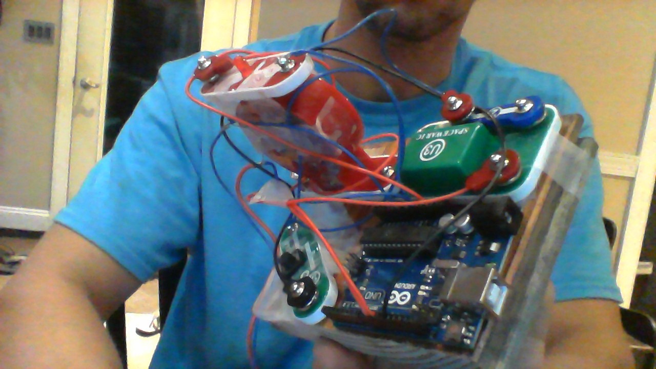
as noted , I used some of my sons snap kit components. I'm waiting on the relays and other supplies so I don't have anything hooked up to that pin.. I did however put a small dc motor on it and it does work.
this is the sad prototype but works perfect!
What would be a good WiFi shield that can be added to this project? My thoughts are maybe adding a mic, timer/stopwatch and IR wifi camera. This would allow us to srteam to a cloud and use our smart phones to keep an I on him as well as log Data.
OK, I tried removing the line of code. However, even with the threshold set at "1" it's not sensitive enough. Is it going to hurt anything if it's consistently is reporting? as it stands now, everything works great. but I'm worried about the "none"movement part. If its always reporting movement, it will need to be filtered out some how? Maybe a pot in place of the 1 megohm resistor would do the trick? that would allow me to adjust it until no movement is sensed without interfering with the code...
Not a problem it it's reporting a few values constantly...if those values come from actual movement/sound.
How long is the wiring to the piezo. You might have to use shielded wire if it's longer than ~20cm.
The statement: if (piezoValue > 0) { // if there is any movement
can be changed into: if (piezoValue > 10) { // if there is some movement
Then very small movements are ignored.
Leo..
I am actually using his old movement sensor mat at this time. it has a 35mm peizo in it with a nice spring loaded plastic housing that is about 12" X 12"... The cable is about 8 ft long and is shielded. He just woke up from his nap so now will be a good time to change some settings.
Thanks!
That fixed everything! This is what I changed them to for now.
if (piezoValue > 20) { // if there is any movement
    Serial.print(F("Piezo value is "));
    Serial.println(piezoValue); // print the value
    ledValue = map(piezoValue, 15, 1023, 15, 255); // map to PWM range
is it going to to a big deal to add the "none" movement part?
kaz321:
is it going to to a big deal to add the "none" movement part?
Please explain.
Setting a small threshold is only affecting reporting (LED and serial monitor).
Leo..