If the CPU is serial TTL (5V) yes.
Can I describe the commands format mentioned in ascii/hex with Arduino to send each character (8-bit) with LSB first ?
Yes
From the Arduiono is like this
If the CPU is serial TTL (5V) yes.
Can I describe the commands format mentioned in ascii/hex with Arduino to send each character (8-bit) with LSB first ?
Yes
From the Arduiono is like this
The frequency of MAX232 on my device is 171KHz. If I use Arduino Nano/Uno to communicate with a CPU on board (bypass the MAX232). Is this possible ? The PWM pin on Arduino Uno has 1Khz max. Is this the same for Tx, Rx pins ?
It is possible but will require some special software. However I do not have the time right now to write it.
Maybe someone else can help.
I'm not clear on what you are referring to here - is it the baud rate - which is an odd value but odd values are sometimes used.
No, PWM and UART baud rate are completely unrelated.
Is that measured during data transfer? If not, what and where are you measuring. And with what measuring device?
Frequency is measured at pin 1, 3, 4, 5.
Amplitude max ~ 8V at pin 1 but Voffset = 4V.
Amplitude ~ 4Vpp at pin 3.
Amplitude ~ 8Vpp at pin 4
Amplitude ~ -8Vpp at pin 5
Measured at normal without data transfer.
Is this frequency (171 KHz) is from external capacitors ? How calculus ?
You are measuring the frequency of the switching of your doubler and the inverter, NOT THE FREQUENCY OF THE DATA PINS!
Exactly ! The data baud rate is set at 9600 as recommended for RS232.
And there is no frequency to be read from the data pins!
Do you have an example Arduino (nano) coding that I can apply to send the data (as "503 0 1E") to a MCU through UART link ?
Thanks for any advises,
V5D
A simple one line of code like this (modified for your chosen serial port) should suffice:
Serial.print("501 0 1E");
However, unless I've missed it, we are around post #50 in this discussion and it's still not clear how the data should be formatted for the display.
I suspect that the "501 0 1E" is an example provided by the Excalibur software documentation and not what the display actually needs or expects.
No, this is the command from display unit manual for maintenance and test the unit. This command can (tell the hardware) reset an GPIO HIGH/LOW logic level for test or to display a pattern grey image,...
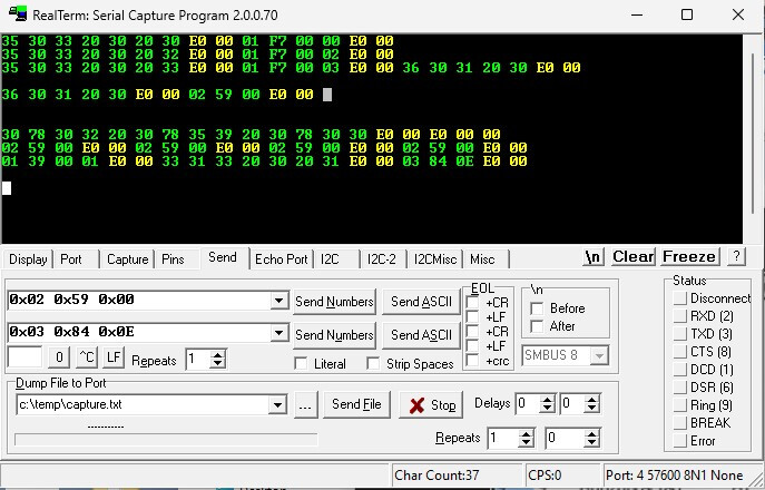
I don't understand well if I can use Tera Term or Real Term to send this command to their MCU or I have to use un Arduino (Nano, Uno) ?
I would suggest a PC based terminal emulator like TeraTerm or RealTerm - whichever you are familiar with - and the appropriate USB-RS232 dongle as a starter. That way you are not having to deal with wiring from your Arduino to an RS232 adapter.
It seems a good way to do.
Thanks for response.
I use the RealTerm to send a command "1 1" (1 "space" 1) as ASCII.
I got this signal CH2 below (at pin 12 of RX232):
It seems correct. Could you please double check ?
Thank you.
Sending 1 then SPACE then 1 should output ASCII codes 31 (hex), 20 and 31. The scope trace appears to show that.
No, do you? It's your device.
I see. This is a test with a good unit that I have (meaning it doesn't display an "T" or "F" letter).
In ASCII table, "E0" is an "alpha" character, "00" is NULL: maybe that means "no problem" for these commands (hope so).
I haven't got a clue! Like I mentioned several posts ago, the messages and their contents are likely to be proprietary information. It's possible that you could figure it out if you had a lot of time and were methodical about it.
You really need the manufacturers documentation - there will be a document that details the messages and their contents.
You could come at it by looking at the documentation for the device that talks to the display and see if that details any messages.