How-to-use-the-ESP8266-01-pins states
The ESP-01S has 12K pullup resistors on the board for GPIO0, RST and CH_PD
checked and the device I am using is a ESP-01S
I assume you were using a ESP-01
I'll do that for sure!
Yeah, that's for sure doing the necessary to make it operational! Dumb me!
I know how it works. I wasn't just thinking about the other pins as I was so focused on the Tx and Rx pins and how you guys had them connected and I wasn't able to do anything! My bad! But this is a learning process to me. I'm not experienced. I'm only working in this area (embedded systems) for a couple of months now!.
1 Like
I've been trying to do something a bit different and closer to what I need to do in my project.
I have created an array of floats, put some random values inside it and tried to send that array, index by index, to ESP01 via Serial1 but I can't see anything arriving at ESP01, where I'm listening in Serial.
This is the code I'm using in Arduino:
float data[10] = {4.8, 6.1, 7.4, 8.5, 9.1, 10.5, 11, 12.2, 15, 22};

void setup(){
    Serial.begin(115200);
    Serial1.begin(115200);
}

void loop(){
    for(int i = 0; i < 10; i++){
        Serial1.write(data[i]);
        delay(50);
    }
}
The code in ESP01 is this:
#include <ESP8266WiFi.h>

WiFiClient espClient;

// Access credentials for WiFi connection
const char* ssid = "xxxxxxxxxxx";
const char* password = "xxxxxxxxxxxxxxxxxx";

char data[10] = {0};
int charsRead = 0;

void setup(){
    delay(5000);
    Serial.begin(115200);
    // We start by connecting to a WiFi network
    Serial.print("Connecting to ");
    Serial.println(ssid);

    WiFi.mode(WIFI_STA);
    WiFi.begin(ssid, password);

    while (WiFi.status() != WL_CONNECTED) {
      delay(500);
      Serial.print(".");
    }

    Serial.println("");
    Serial.println("WiFi connected");
    Serial.println("IP address: ");
    Serial.println(WiFi.localIP());
}

void loop(){
    while(Serial.available() > 0)
        charsRead = Serial.readBytes(data, 10);
    if (charsRead){
        digitalWrite(1, HIGH);
        Serial.print(data);
        // Serial.println(" from ESP01!");
        charsRead = 0;
		data[10] = {0};
        delay(500);
        digitalWrite(1, LOW);
    }
    else
        Serial.println('1');
    delay(500);
}
Why can't I see the values in ESP01 serial port? I can only see ones, as if anything was getting there!
what 'Arduino' are you using?
could you upload a schematic showing your wiring?
ESP-01 connected to a ESP32

ESP-01 program echos text received in URX0 to UTX0
//  ESP-01 blink LED and read characters from serial U0RXD  and echo back to U0TXD

void setup() {
  Serial.begin(115200);
  delay(1000);
  Serial.println();
  Serial.println("\n\nESP-01 blinking LED and read characters from serial U0RXD  and echo back to U0TXD ");
  Serial.println(LED_BUILTIN);
  // initialize digital pin LED_BUILTIN as an output.
  pinMode(LED_BUILTIN, OUTPUT);
}

void loop() {
  digitalWrite(LED_BUILTIN, HIGH);  // turn the LED on (HIGH is the voltage level)
  delay(100);                       // wait for a second
  digitalWrite(LED_BUILTIN, LOW);   // turn the LED off by making the voltage LOW
  delay(100);                       // wait for a second
  // read serial U0RXD and echo it back to U0TXD
  while (Serial.available() > 0) {
    char ch = Serial.read();
    Serial.write(ch);
  }
}
ESP32 transmits float array to ESP-01 and displays response received
// ESP32  Serial1 test - transmit float array to Serial1 dusplay response

#define RXD1 16
#define TXD1 15

void setup() {
  // initialize both serial ports:
  Serial.begin(115200);
  Serial1.begin(115200, SERIAL_8N1, RXD1, TXD1);
  Serial.println();
  Serial.println("\n\nESP32 serial1  test Rx pin 16 Tx pin 15");
}

void loop() {
  static float data[10] = { 4.8, 6.1, 7.4, 8.5, 9.1, 10.5, 11, 12.2, 15, 22 };
  static long timer = millis() + 11000;
  // transmit flaot array every 2 seconds to Serial1
  if (millis() - timer > 2000) {
    for (int i = 0; i < 10; i++) {
      Serial1.print(data[i]);
      delay(50);
    }
    Serial1.println();
    data[0] += 1.0;  // increment data[0] to show something is happening
    timer = millis();
  }
  // read from port 1, send to port 0:
  while (Serial1.available()) {
    int inByte = Serial1.read();
    Serial.write(inByte);
  }
}
ESP32 serial monitor displays
ESP32 serial1  test Rx pin 16 Tx pin 15
4.806.107.408.509.1010.5011.0012.2015.0022.00
5.806.107.408.509.1010.5011.0012.2015.0022.00
6.806.107.408.509.1010.5011.0012.2015.0022.00
7.806.107.408.509.1010.5011.0012.2015.0022.00
8.806.107.408.509.1010.5011.0012.2015.0022.00
9.806.107.408.509.1010.5011.0012.2015.0022.00
10.806.107.408.509.1010.5011.0012.2015.0022.00
11.806.107.408.509.1010.5011.0012.2015.0022.00
12.806.107.408.509.1010.5011.0012.2015.0022.00
13.806.107.408.509.1010.5011.0012.2015.0022.00
14.806.107.408.509.1010.5011.0012.2015.0022.00
15.806.107.408.509.1010.5011.0012.2015.0022.00
16.806.107.408.509.1010.5011.0012.2015.0022.00
17.806.107.408.509.1010.5011.0012.2015.0022.00
The Arduino is the same Nano 33 BLE Sense.
The wiring is the same as your example. I mean Rx to Tx and vice-versa. Common GND and 3v3. That's all.
I'll be reading your code and will try to check what are the differences to mine and will troubleshoot things to see if I can make this work!
Thanks
looking at nano-33-ble-sense/uart you should be able to connect the ESP-01 to the Serial1 UART Rx and Tx pins
similar code to my ESP32 program in post 69 should run on the nano 33 BLE sense and communicate with the ESP-01
Just clear a few questions.
In your example of #69, who is the receiver and who is the transmitter?
In my case, my Nano needs to be the transmitter and the ESP01 needs to be the receiver!
From what I see in your post #69, ESP01 seems to be the receiver and ESP32 the transmitter, yes?
post #69 was a test of functionality
- the ESP32 sent the array over serial to the ESP-01
- the ESP-01 received the serial data and echoed it back to the ESP32
- the ESP32 receives the echoed data and prints it
this shows the ESP-01 can receive serial data and do something with it
in your case
- the nano sends the array over serial to the ESP-01
- the ESP-01 receives the data and sends it over WiFi to ????
where is the data going over WiFi? e.g.
- put it on a web page so it can be viewed remotly?
- transmit it using MQTT to a remote desktop?
????
1 Like
Ok, so I uploaded this code to the Arduino:
// ESP32  Serial1 test - transmit float array to Serial1 dusplay response

// #define RXD1 16 < -- Removed
// #define TXD1 15 < -- Removed

void setup() {
  // initialize both serial ports:
  Serial.begin(115200);
  Serial1.begin(115200 /*, SERIAL_8N1, RXD1, TXD1 - REMOVED*/);
  Serial.println();
  Serial.println("\n\nESP32 serial1  test Rx pin 16 Tx pin 15");
}

void loop() {
  static float data[10] = { 4.8, 6.1, 7.4, 8.5, 9.1, 10.5, 11, 12.2, 15, 22 };
  static long timer = millis() + 11000;
  // transmit flaot array every 2 seconds to Serial1
  if (millis() - timer > 2000) {
    for (int i = 0; i < 10; i++) {
      Serial1.print(data[i]);
      delay(50);
    }
    Serial1.println();
    data[0] += 1.0;  // increment data[0] to show something is happening
    timer = millis();
  }
  // read from port 1, send to port 0:
  while (Serial1.available()) {
    int inByte = Serial1.read();
    Serial.write(inByte);
  }
}
and put this in ESP01:
//  ESP-01 blink LED and read characters from serial U0RXD  and echo back to U0TXD

void setup() {
  Serial.begin(115200);
  delay(1000);
  Serial.println();
  Serial.println("\n\nESP-01 blinking LED and read characters from serial U0RXD  and echo back to U0TXD ");
  Serial.println(LED_BUILTIN);
  // initialize digital pin LED_BUILTIN as an output.
  pinMode(LED_BUILTIN, OUTPUT);
}

void loop() {
  digitalWrite(LED_BUILTIN, HIGH);  // turn the LED on (HIGH is the voltage level)
  delay(100);                       // wait for a second
  digitalWrite(LED_BUILTIN, LOW);   // turn the LED off by making the voltage LOW
  delay(100);                       // wait for a second
  // read serial U0RXD and echo it back to U0TXD
  while (Serial.available() > 0) {
    char ch = Serial.read();
    Serial.write(ch);
  }
}
And this is the only thing I can see in Arduino Serial monitor:
Ǝ�����ƒ�
ESP-01 blinking LED and read characters from serial U0RXD and echo back to U0TXD
2
and the same on ESP01 side:
l ��n�l
ESP-01 blinking LED and read characters from serial U0RXD and echo back to U0TXD
2
And why you add 11000 to the millis() function in Arduino code?
the 11000 is just to start the ESP32 transmitting immediatly
how have you wired the nano to the ESP-01?
it is ESP-01 mounted in a programmer or just connected by wires to the nano?
how do you power the ESP-01 ? from the nano?
This is all mounted on a perfurated circuit board. I am feeding the board with an external power supply of 12V into a step-down converter which feeds the Nano and the ESP01 at 3v3.
Nano and ESP01 are connected together with soldered wires.
The ESP01 is also on the perfurated circuit board mounted on those 4x2 pin headers. And I have another 4x2 pin header where I connect an USB-to-TTL converter to program the ESP01.
Already answered above. But it is being powered from the step-down converter.
which pins are connected?

when you have programed the ESP-01 and then execute the code do you disconnect the programmer from the ESP-01 Rx (GPIO3) and TX (GPIO1) lines otherwise the nano to ESP-01 communication won't work
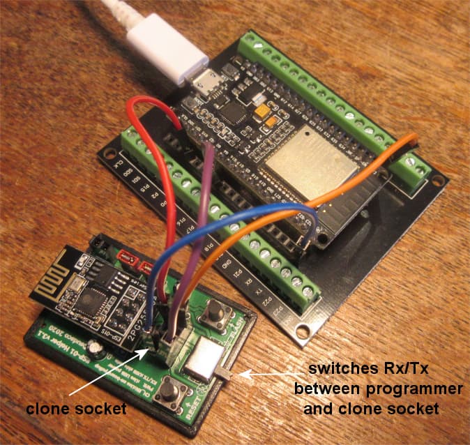
the programmer I use has a switch which switches the ESP-01 Rx/TX lines between the USB programmer and the clone socket where the RX/TX are connected to the ESP32 TX/RX, e.g.
Hum, ok, will try to disconnect the lines. Not sure if I tried that.
You were right. I can see the stuff working on my Arduino Serial port!
Now, I'll try to work the code to make it the other way around. I want to send from Arduino to ESP01 and see it on ESP01 Serial port.
@horace can you please detail a bit further the 11000 value? And why you use the millis() function and then you use the delay() function? Couldn't we simply use the dealy() ?
Also, what is the Serial.println() for? Just to print a new line char?
And I have another question.
In your Arduino (ESP32 in you case) code, you send the array to port 1 of Serial, right? So, when you prrint to port 1 of Serial in Arduino, the ESP01 will listen at its port 0 of Serial, yes?