basically this code query to solar inverter and in return print the reply from solar inverter originally copied it from "https://www.youtube.com/watch?v=Ri2HvdjnINw&list=PLDW1zKN_tjaJDp-Ukz8KApchBgA60AFC_&index=9&ab_channel=545sytes"
the code upload easily but on serial monitor i don have any print also my blue light on ESP-01 blinks very dim but if replace the pins 0,2 with hardware RX and TX the code works as desired but in this scenario i am unable to get any reply on serial monitor.
Your topic has been moved. Please do not post in "Uncategorized"; see the sticky topics in Uncategorized - Arduino Forum.
Please edit your post, select all code and click the <CODE/> button; next save your post. This will apply so-called code tags which makes the code easier to read and copy and the forum software will display it correctly.
Never personally tried this, but if you want, try.
Since esp8266 has UART1 TX1 on Gpio2 and you only need to tx to serial monitor, you could use Serial (Gpio1&3) for inverter and Serial1 (Gpio2) for serial monitor.
So all without softwareserial.
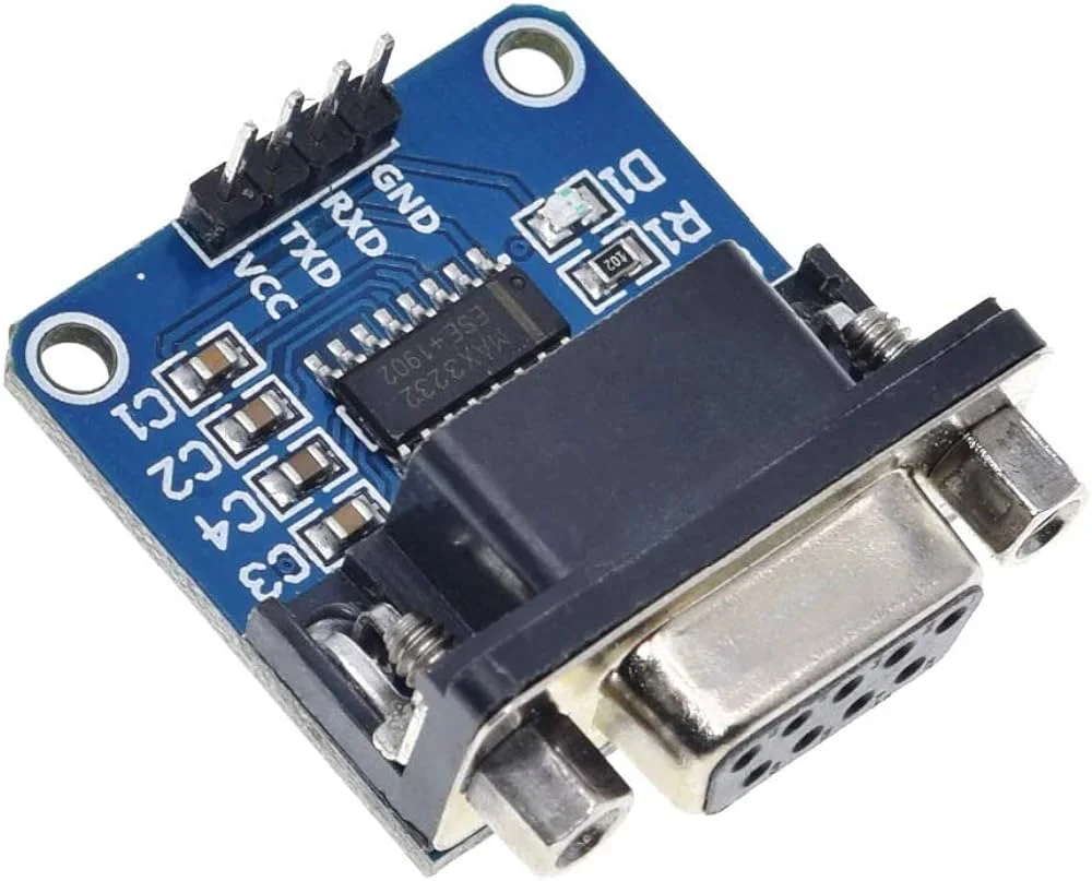
i am connecting the RX of ESP-01 with TX of Rs232-ttl converter. similarly TX of ESP-01 with RX of Rs232-ttl converter to send and receive the commands
To program your Esp just use it as normally. If you want to connect Serial rx0/tx0 to inverter and Serial1 tx1 to that "programmer", you need to use dupont wires.
Your life would be much easier with Esp32 devboard.
After programming GPIO 0 should not be connected to GND anymore.
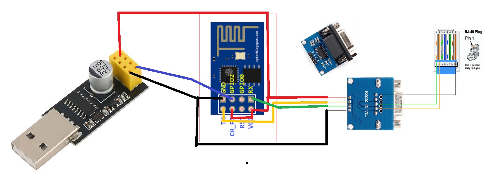
instead of connecting ESP-RX to the programmer, just connect it to the converter.
Connect TX of the programmer to GPIO 2 of the ESP.
Use Serial1 for the debug and Serial for the connection to the converter.
Please update the drawing and upload the new code, so we can see that you understand correctly or we need to improve on the explanation
Eh have you now connected ESP RX to converter RX (instead of TX) ? It's a little hard to tell because you've turned the converter over in the newest version. For the rest that looks fine.
I would probably test for anything being in the buffer before reading and printing it, and make 'stringOne' a local variable and 'QPIGS' a constant, but if it worked like this before it should work now.
ESP RX is connected to TX of Converter yes i have changed the picture. well many thanks for the code i will try and update you as soon as i get any success. many thanks for the code again
Please add a resistor in between pins on each line to limit the current or you may damage your ESP (and possibly the converter) something like 10K will be fine for slow speeds.
no just between esp & converter TX & RX. Particularly if you are going to start swapping them over ! if two TX lines are connected they may break otherwise. Hopefully not since there would be no reception on the RX line and so no response, but still it may happen.