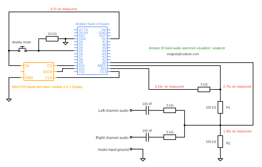
The Arduino is sharing a power supply with the Bluetooth board and as a result I believe suffering from a ground loop.
The Audio visualiser requires the negative side of the audio outputs be connected to ground. I assume the Arduino requires this to measure the audio output.
I can get the the audio visualiser working if I use a separate power supply (usb) but my project requires that the Arduino and audio board share a power supply.
Is there some way of letting the Arduino and the audio board share a ground on the power supply and separate the audio output negative for the Arduino to measure?
Thanks. As I understand the problem occurs when the audio board is involved, connected to the same power source. I hoped for a wiring showing how You connected the lot.
Data sheet of the audio board is highly wanted....
Did You check the need for current? Do those two boards draw too much current, more than the supply delivers and therefore the problem?
Railroader:
Thanks. As I understand the problem occurs when the audio board is involved, connected to the same power source. I hoped for a wiring showing how You connected the lot.
Data sheet of the audio board is highly wanted....
Did You check the need for current? Do those two boards draw too much current, more than the supply delivers and therefore the problem?
Here is a video demonstrating the issue I currently have.
The power supply I'm using is a 240v AC to 24v DC 1A inverter. The audio board max amps is 3A. I'm using a voltage reducing buck to turn the voltage down to 9v for the Arduino. I believe 2A is recommended for the Arduino?
So it looks like my supply isn't giving enough amps. Cod this be causing the issue in the video?
Ok. However I recommend a direct, stabilised +5 volt directly to the controller 5 volt pin. Using the UNO onboard 5 volt converter gives You almost no possibility to spend current on the outputs. One LED, maybe 2, then that not cooled 5 volt converter is overloaded.
nathrouty:
The idea of the 9v input was to ensure a reliable 5v output from the Arduino.
Which is of course, dead wrong!
While some people do suggest using the on-board regulator to minimise ripple on the 5 V, this regulator has little or no heatsink and can only supply perhaps 100 mA before overheating and (hopefully reversibly,) shutting down or at least failing to regulate. Its very existence is a rather nasty trap for naïve players!
You have shown a MAX7219 module attached to this 5 V - with all of 4 digits lit, this would draw at least 160 mA on its own and generate a considerable amount of ripple in any case, so any benefit of the series regulator in providing a smooth supply is immediately lost.
At the very least you require two capacitors - 100 µF and 100 nF - across AREF.