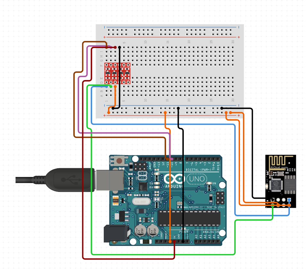
Hi everybody. I need to use an adafruit huzzah feather esp8266 to connect my arduino UNO to WiFi and send orders with a smartphone. I power my esp by connecting it to the 3.3V pin on arduino (my teacher told me to do like that). I have problems with the serial comunication between the 2 boards (I'm using pin 0 and 1 on UNO and TX an RX on esp). Could somebody help me please ![]() ?
?
here is the esp code
void setup() {
  Serial.begin(9600);
}

void loop() {
  Serial.println('H');
  delay(1000);
  Serial.println('s');
  delay(500);

  Serial.println('B');
  delay(1000);
  Serial.println('s');
  delay(500);
}
and here is a part of what's in my void loop
if (Serial.available()) {
    ordre = Serial.read();

    switch (ordre) {
      case 'H':     //moteur glissière en haut
        if (digitalRead(pinArretUrgence) == LOW && digitalRead(pinFdcHaut) == HIGH) {
          digitalWrite(sensMotGlisseur, LOW);
          analogWrite(vitMotGlisseur, sixVolts);
        }
        break;

      case 'B':    //moteur glissière en bas
        if (digitalRead(pinArretUrgence) == LOW && digitalRead(pinFcdBas) == HIGH) {
          digitalWrite(sensMotGlisseur, HIGH);
          analogWrite(vitMotGlisseur, sixVolts);
        }
        break;
Am I right in thinking the Uno is 5v? If so you will need a logic level shifter. If you have powered it up you have probably blown the ESP 8266 as they are very fussy about what voltage you give them. I think they max out at about 3.7v before doing damage.
I connected the esp to the 3.3V pin on arduino, and it's still working (the LED light up)
That's fine for the power but what about the communication pins? I believe you will need to set it up something like this:
// Include Libraries
#include "Arduino.h"
#include "ESP8266.h"


// Pin Definitions
#define WIFI_PIN_TX	11
#define WIFI_PIN_RX	10


// Global variables and defines
// ====================================================================
// vvvvvvvvvvvvvvvvvvvv ENTER YOUR WI-FI SETTINGS  vvvvvvvvvvvvvvvvvvvv
//
const char *SSID     = "WIFI-SSID"; // Enter your Wi-Fi name
const char *PASSWORD = "PASSWORD" ; // Enter your Wi-Fi password
//
// ^^^^^^^^^^^^^^^^^^^^^^^^^^^^^^^^^^^^^^^^^^^^^^^^^^^^^^^^^^^^^^^^^^^^
// ====================================================================
char* const host = "www.google.com";
int hostPort = 80;
// object initialization
ESP8266 wifi(WIFI_PIN_RX,WIFI_PIN_TX);


// define vars for testing menu
const int timeout = 10000;       //define timeout of 10 sec
char menuOption = 0;
long time0;

// Setup the essentials for your circuit to work. It runs first every time your circuit is powered with electricity.
void setup()
{
    // Setup Serial which is useful for debugging
    // Use the Serial Monitor to view printed messages
    Serial.begin(9600);
    while (!Serial) ; // wait for serial port to connect. Needed for native USB
    Serial.println("start");

    wifi.init(SSID, PASSWORD);
    menuOption = menu();

}

// Main logic of your circuit. It defines the interaction between the components you selected. After setup, it runs over and over again, in an eternal loop.
void loop()
{


    if(menuOption == '1') {
    // ESP8266-01 - Wifi Module - Test Code
    //Send request for www.google.com at port 80
    wifi.httpGet(host, hostPort);
    // get response buffer. Note that it is set to 250 bytes due to the Arduino low memory
    char* wifiBuf = wifi.getBuffer();
    //Comment out to print the buffer to Serial Monitor
    //for(int i=0; i< MAX_BUFFER_SIZE ; i++)
    //  Serial.print(wifiBuf[i]);
    //search buffer for the date and time and print it to the serial monitor. This is GMT time!
    char *wifiDateIdx = strstr (wifiBuf, "Date");
    for (int i = 0; wifiDateIdx[i] != '\n' ; i++)
    Serial.print(wifiDateIdx[i]);

    }

    if (millis() - time0 > timeout)
    {
        menuOption = menu();
    }

}


// Menu function for selecting the components to be tested
// Follow serial monitor for instructions
char menu()
{

    Serial.println(F("\nWhich component would you like to test?"));
    Serial.println(F("(1) ESP8266-01 - Wifi Module"));
    Serial.println(F("(menu) send anything else or press on board reset button\n"));
    while (!Serial.available());

    // Read data from serial monitor if received
    while (Serial.available())
    {
        char c = Serial.read();
        if (isAlphaNumeric(c))
        {

            if(c == '1')
    			Serial.println(F("Now Testing ESP8266-01 - Wifi Module"));
            else
            {
                Serial.println(F("illegal input!"));
                return 0;
            }
            time0 = millis();
            return c;
        }
    }
}
The red pcb on the breadboard is a logic level shifter to ensure signals are stepped down and up from 5V - 3V and vice versa
Why do you need the Uno? What can you not do with the esp8266?
Not such a great idea. The red light might be all you are getting, and the last thing you actually need. About the most you can expect from the 3.3v is 150mA, and it may be a lot less.
I guess you have to do this just for the intellectual exercise, but the Uno is probably redundant, and serves as no more than an ill-chosen power supply.
Your teacher seems not to know not much about ESP8266s.
On WiFi sending there are short current-spikes up to 300 mA which the arduino can not deliver.
This can cause that the ESP8266 does a reset. (through brown-out = voltages drops to a too low value)
What might help is a 2000 µF capacirot connected very close to the ESP8266 Vcc and GND-pins. The capacitor will "jump in" to keep the voltage high in case of such a short current-spike.
As a mimium the Arduino-Tx-pin must be connected to the ESP8266-Rx-pin through a voltage-divider that reduces the voltage from 5V to 3.3V
What shall the Arduino do in this project?
the adafruit huzzah feather esp8266 has IO-pins. Depending on what the arduino shall do the arduino might be completely kicked out because the adafruit huzzah feather esp8266 can do it all.
best regards Stefan
I need the Uno to control motors and a servo
ESP chips can control motors and servos.
Depending on how this works and how many motors and servos
= how many IO-pins this requires this can be done by the ESP8266 itself.
best regards Stefan
I'm using a motor shield. I also need a bunch of buttons. I know it's absolutely not optimized but that's how I'm supposed to do it ![]()
I control 2 motors with the shield, 1 servo and 1 fan with the UNO, and I have 5 inputs buttons
This topic was automatically closed 180 days after the last reply. New replies are no longer allowed.