Serial Connection Shutting Down When Powering a Relay [Solved]

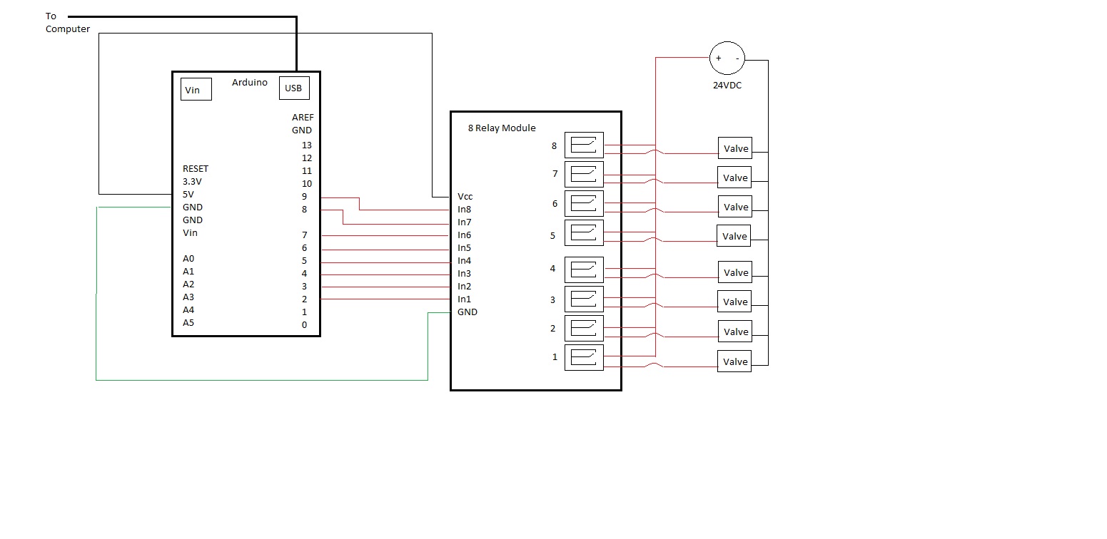
I have an Arduino Uno which has pins 2-9 connected to an 8 relay module. The module is rated for 5V actuating 24VDC. If you need the specs I'm happy to get them but they're not in this post cause it's a pretty standard relay module.

I have code attached below which accepts serial input to set the arduino pins (2-9) high or low to actuate the relays. The relays are connected to valves which can be turned on and off through the serial monitor (or in practice a processing sketch). In addition, the sketch reads data off analog pins 0 and 1 every second and sends that data along with some other information back to the serial monitor. The VCC bit at the end is supposed to help adjust for the fact that the 5V reference isn't exactly 5V and it's slightly different on each arduino. That section of code seems to work fine for it's purpose.

The Problem
The code works great to actuate the relays depending on what I input into the serial monitor. However, when I turn on the power supply so the relays will actually close and power the valves, the program hangs up after a couple relays are switched.
If I type 2 to turn on relay 1, it turns on. When I type 2 again to turn it off, I think my Serial connection over USB breaks (based on println() I've seen in stop in both the for loop and the switch statement, sometimes stopping in the middle of printing a Serial.println().) The Tx light keeps flashing but the serial monitor stop listing the data. If I send the arduino another command over the Serial monitor I get the error listed in the next post.

Here's the code:

/* 
 This program accepts Serial inputs to toggle the state of pins 2-8 between high and low upon receiving a string with the corresponding pin as the first character.  
 Input strings are limited to 10 chars.
 In addition, it accepts the character 9 followed by 3 characters to set the PWM Value of pin 9 (i.e. '9123' sets pin 9 to 123).
 It also sends out a serial string which is 'A0,A1,pause, Vcc' where A0 and A1 are the values of the corresponding analog pins, 
 pause is the time in milliseconds between serial outputs, and Vcc is the measured voltage of default 5V pin.
 */
int timesThrough = 0;
String output1;  //data point 1
String output2;  //data point 2
int pause = 1000;  //loop delay in ms
char input[4];
char input1;
char input2;
char input3;
char input4;
int pumpSpeed = 0;

void setup()  {  //9600 baud serial monitor output
  Serial.begin(9600);
  for(int i = 2; i<11;i++)
  {
    pinMode(i, OUTPUT);
    digitalWrite(i, HIGH);
  }
  digitalWrite(10,LOW);
}

void loop() {
  if(Serial.available())
  {

    for(int j = 0; j < 4; j++)
    {
      //Serial.println(j);
        input[j] = Serial.read();
      delay(5);
      //Serial.println(input[j]);

    }
    
    switch(input[0])
    {
    case '1':
      if(digitalRead(9)==HIGH)  
      {
        digitalWrite(9,LOW);
      }
      else
      {
        digitalWrite(9,HIGH);
      }
      break;

    case '2':
      if(digitalRead(2)==HIGH)  
      {  
        
        digitalWrite(2,LOW);
      }
      else
      {
        
        digitalWrite(2,HIGH);
      }
      break;

    case '3':
      if(digitalRead(3)==HIGH)  
      { 
        digitalWrite(3,LOW);
      }
      else
      {
        digitalWrite(3,HIGH);
      }
      break;

    case '4':
      if(digitalRead(4)==HIGH)  
      {  
        digitalWrite(4,LOW);
      }
      else
      {
        digitalWrite(4,HIGH);
      }
      break;

    case '5':
      if(digitalRead(5)==HIGH)  
      {  
        digitalWrite(5,LOW);
      }
      else
      {
        digitalWrite(5,HIGH);
      }
      break;

    case '6':
      if(digitalRead(6)==HIGH)  
      { 
        digitalWrite(6,LOW);
      }
      else
      {
        digitalWrite(6,HIGH);
      }
      break;

    case '7':
      if(digitalRead(7)==HIGH)  
      { 
        digitalWrite(7,LOW);
      }
      else
      {       
        digitalWrite(7,HIGH);
      }
      break;

    case '8':
      if(digitalRead(8)==HIGH)  
      { 
        digitalWrite(8,LOW);
      }
      else
      {
        digitalWrite(8,HIGH);
      }
      break;

    case '9':
      pumpSpeed = 0;
      for(int k = 1; k < 4;k++)       //code that should work that doesn't
      {
        int value = (input[k]-'0');
        int power = round(pow(10,(3-k)));

       pumpSpeed += value*power;
        

      }
      //Serial.println(pumpSpeed);
      if(pumpSpeed == 0)
      {
        digitalWrite(10,LOW);
      }
      else
      {
        analogWrite(10, pumpSpeed);
      }     
      break;

    default:
      break;
    }
  }
  if(millis() / (pause-1) > timesThrough)  //send data every 'pause' in ms
  {
    analogReference(DEFAULT);  //set reference to 5V
    output1 = String(analogRead(A0));  //read analog pin A0
    output1 = String(analogRead(A0));  //read analog pin A0 second time.  Allows time for the analog reference to fully switch
    analogReference(INTERNAL);  //set reference to 1.1V
    output2 = String(analogRead(A1));  //read analog pin A1
    delay(10);                  
    output2 = String(analogRead(A1));  //read analog pin A1 second time.  Allows time for the analog reference to fully switch
    delay(10);                  
    output2 = String(analogRead(A1));   //read analog pin A1 third time.  As above
    delay(10);                    
    Serial.println(output1 + "," + output2 + "," + pause + "," + readVcc() + "," + pumpSpeed);

    //delay(pause);  
    if(digitalRead(13)==HIGH)  {  //flash and led every loop iteration
      digitalWrite(13,LOW);
    }
    else{
      digitalWrite(13,HIGH);
    }
    timesThrough++;  //update count
  }
}

long readVcc() {
  // Read 1.1V reference against AVcc
  // set the reference to Vcc and the measurement to the internal 1.1V reference
#if defined(__AVR_ATmega32U4__) || defined(__AVR_ATmega1280__) || defined(__AVR_ATmega2560__)
  ADMUX = _BV(REFS0) |  _BV(MUX4) | _BV(MUX3) | _BV(MUX2) | _BV(MUX1);
#elif defined (__AVR_ATtiny24__) || defined(__AVR_ATtiny44__) || defined(__AVR_ATtiny84__)
  ADMUX = _BV(MUX5) | _BV(MUX0);
#elif defined (__AVR_ATtiny25__) || defined(__AVR_ATtiny45__) || defined(__AVR_ATtiny85__)
  ADMUX = _BV(MUX3) | _BV(MUX2);
#else
  ADMUX = _BV(REFS0) | _BV(MUX3) | _BV(MUX2) | _BV(MUX1);
#endif 


  delay(2); // Wait for Vref to settle
  ADCSRA |= _BV(ADSC); // Start conversion
  while (bit_is_set(ADCSRA,ADSC)); // measuring

  /*uint8_t low  = ADCL; // must read ADCL first - it then locks ADCH  
   uint8_t high = ADCH; // unlocks both
   
   long result = (high<<8) | low;
   result = 2618880L / result; // Calculate Vcc (in mV); 1125300 = 1.1*1023*1000*/
  long result = 1125300 / ADC; // Calculate Vcc (in mV); 1125300 = 1.1*1023*1000
  return result; // Vcc in millivolts

}

What I've Tried Serial.read() returns -1 when there's nothing and I've verified that it's fine being called when there's nothing to read. With println() statements I've seen it capture the -1 perfectly fine. I've also tried bracketing the Serial.read with if(Serial.available()) so it wouldn't call the read if there wasn't anything more for it. I also tried removing the char array and string each byte into it's own char variable manually which doesn't solve the problem either. It seems like the serial communication is breaking as the arduino is still trying to send data, according to the Tx light, but the serial monitor doesn't seem to receive it. The most confusing part of this is that if I unplug the power source from the relay so the valves don't actually flip, (relays still turn on and off) then the program works fine. So maybe there's a feedback problem or something... Any help would be greatly appreciated.

If I try to enter another serial command while it's hung up, I get this error.

java.io.IOException: Input/output error in writeArray
	at gnu.io.RXTXPort.writeArray(Native Method)
	at gnu.io.RXTXPort$SerialOutputStream.write(RXTXPort.java:1124)
	at processing.app.Serial.write(Serial.java:517)
	at processing.app.Serial.write(Serial.java:540)
	at processing.app.SerialMonitor.send(SerialMonitor.java:200)
	at processing.app.SerialMonitor.access$100(SerialMonitor.java:32)
	at processing.app.SerialMonitor$3.actionPerformed(SerialMonitor.java:89)
	at javax.swing.JTextField.fireActionPerformed(JTextField.java:492)
	at javax.swing.JTextField.postActionEvent(JTextField.java:705)
	at javax.swing.JTextField$NotifyAction.actionPerformed(JTextField.java:820)
	at javax.swing.SwingUtilities.notifyAction(SwingUtilities.java:1636)
	at javax.swing.JComponent.processKeyBinding(JComponent.java:2851)
	at javax.swing.JComponent.processKeyBindings(JComponent.java:2886)
	at javax.swing.JComponent.processKeyEvent(JComponent.java:2814)
	at java.awt.Component.processEvent(Component.java:6040)
	at java.awt.Container.processEvent(Container.java:2041)
	at java.awt.Component.dispatchEventImpl(Component.java:4630)
	at java.awt.Container.dispatchEventImpl(Container.java:2099)
	at java.awt.Component.dispatchEvent(Component.java:4460)
	at java.awt.KeyboardFocusManager.redispatchEvent(KeyboardFocusManager.java:1848)
	at java.awt.DefaultKeyboardFocusManager.dispatchKeyEvent(DefaultKeyboardFocusManager.java:704)
	at java.awt.DefaultKeyboardFocusManager.preDispatchKeyEvent(DefaultKeyboardFocusManager.java:969)
	at java.awt.DefaultKeyboardFocusManager.typeAheadAssertions(DefaultKeyboardFocusManager.java:841)
	at java.awt.DefaultKeyboardFocusManager.dispatchEvent(DefaultKeyboardFocusManager.java:668)
	at java.awt.Component.dispatchEventImpl(Component.java:4502)
	at java.awt.Container.dispatchEventImpl(Container.java:2099)
	at java.awt.Window.dispatchEventImpl(Window.java:2475)
	at java.awt.Component.dispatchEvent(Component.java:4460)
	at java.awt.EventQueue.dispatchEvent(EventQueue.java:599)
	at java.awt.EventDispatchThread.pumpOneEventForFilters(EventDispatchThread.java:269)
	at java.awt.EventDispatchThread.pumpEventsForFilter(EventDispatchThread.java:184)
	at java.awt.EventDispatchThread.pumpEventsForHierarchy(EventDispatchThread.java:174)
	at java.awt.EventDispatchThread.pumpEvents(EventDispatchThread.java:169)
	at java.awt.EventDispatchThread.pumpEvents(EventDispatchThread.java:161)
	at java.awt.EventDispatchThread.run(EventDispatchThread.java:122)
  if(Serial.available())
  {

    for(int j = 0; j < 4; j++)
    {
      //Serial.println(j);
        input[j] = Serial.read();

If there is at least one byte to be read, read all 4 of them. Nonsense.

Hi Paul, I realize it's not the "best" code use, but it shouldn't cause an error. Serial.read() checks to see if the buffer tail is in front of the head (i.e. if the string is empty) and returns a -1 if it's empty. So Serial.read() either returns the character if there is one or a -1 if there isn't which suits my purpose and speeds up the program.

I've tried putting a if(Serial.available()) before each read in the for loop. That doesn't solve the problem. I've also ensured that 4 bytes were sent each time in the Serial Monitor and it still seems to close the serial connection to the arduino. I've also put println()'s throughout the program and have found that the Serial.read() works fine returning the -1 ( ÿ ) for input[j] if there's nothing to read.

Also worth noting that the program works and the serial port stays open as long as they valves aren't powered with my 24V power supply. Maybe this belongs in the electronics forum and not the programming forum.

Modified the for loop to this:

if(Serial.available())
  {

    for(int j = 0; j < 1; j++)
    {
      //Serial.println(j);
        input[j] = Serial.read();
  }

So now the for loop only runs once and should always read an input. Program still loses it's serial connection after a few iterations. Sometimes when it disconnects, both the Rx and Tx lights both light up as stay on until the arduino is reset.

Where is the power for the relay coils coming from?

The usual reason for your symptoms is the Arduino resetting because the voltage to it falls when something is switched on which should draws too much current from the Arduino or from its power supply.

...R

The arduino is powered by both the standard USB connection as well as a 19VDC power supply which is also supplying current to the Vin pin. The Vin is used as the voltage source for a pressure transducer. That all worked fine before I installed the relays and valves. The valves are all drawing power from a separate 24 VDC power supply which is only connected to the 24VDC side of the relay where all 8 valves are located in parallel with the power supply. Both power supplies are plugged into the same circuit breaker so maybe when the valves are actuating it's causing a fluctuation in the power available for the 19 VDC supply. Would that make sense? I think it only happens when I'm setting a pin to high which actually takes power off the valve (I'll need to do more to confirm that).

I'll try running without the Vin powered as I don't need the pressure transducer at the moment and I can always power it through the other power supply if that solves it. It's only in it's current configuration out of convenience from a past set up. If my arduino is only powered from the USB, that should remain fairly constant power right? The computer is also plugged into the same circuit as both power supplies but I'd think there's plenty of power in the computer to power a 5V usb and it seems like it must be fairly well regulated so it doesn't fry delicate usb devices.

I think there is something on the Arduino board that enables it to choose power from the USB or the external supply so it is likely it is not drawing power from the USB and, as you surmise, fluctuations are the problem. Coils will have large inrush currents.

I suggest you test by powering the Arduino from the USB only and powering everything else from your other power supplies - with a common ground connection with the Arduino.

...R

Nothing to do with your problem, but I did find this odd

If I type 2 to turn on relay 1, it turns on.

Why not alter the program so that when you type 1 it turns on relay 1 ?

Robin2:
I think there is something on the Arduino board that enables it to choose power from the USB or the external supply so it is likely it is not drawing power from the USB and, as you surmise, fluctuations are the problem. Coils will have large inrush currents.

I suggest you test by powering the Arduino from the USB only and powering everything else from your other power supplies - with a common ground connection with the Arduino.

...R

This - but don't connect the grounds - the relays are there to separate your circuits - a common ground would defeat that.

No common GND between the relay loads and the Arduino, I agree, but a common GND is needed between the power supply for the relays themselves and the Arduino.

It looks like reset the arduino ?

I think the problem comes from the valve (High Voltage Spikes from Inductor Coils), try to unconnect the load from the relay contacts and try again.

One solution is to use MOV (metal oxide varistor) like 10D301K Datasheet(PDF) - World Produts Inc.

Also all the gnd must be connected all together.

I realize it's not the "best" code use, but it shouldn't cause an error. Serial.read() checks to see if the buffer tail is in front of the head (i.e. if the string is empty) and returns a -1 if it's empty. So Serial.read() either returns the character if there is one or a -1 if there isn't which suits my purpose and speeds up the program.

How does having an array with one valid character and three minus ones suit your needs?
I think you should rethink that one.

UKHeliBob:
Nothing to do with your problem, but I did find this odd

If I type 2 to turn on relay 1, it turns on.

Why not alter the program so that when you type 1 it turns on relay 1 ?

Relay 1 is connected to pin 2 on the arduino. So typing 2 changes the state of pin 2, which controls relay 1 and valve 1. It probably should be the way you suggest and maybe I'll change it later but, that's more of an aesthetic issue.

Robin2:
I suggest you test by powering the Arduino from the USB only and powering everything else from your other power supplies - with a common ground connection with the Arduino.

Removed the 19VDC supplying the Vin to the arduino. Also removed the pressure transducer wiring that it was powering just to make sure it wasn't causing an issue. Serial still disconnected when I set a pin high which removes power from the relay and the valve. Definitely seems to only happen on the transition from low to high. Generally on the first occurrence after the setup function.

UKHeliBob:
No common GND between the relay loads and the Arduino, I agree, but a common GND is needed between the power supply for the relays themselves and the Arduino.

The relays are grounded to the arduino board and are powered by the arduino pins. Attached the circuit diagram.

Grumpy_Mike:

I realize it's not the "best" code use, but it shouldn't cause an error. Serial.read() checks to see if the buffer tail is in front of the head (i.e. if the string is empty) and returns a -1 if it's empty. So Serial.read() either returns the character if there is one or a -1 if there isn't which suits my purpose and speeds up the program.

How does having an array with one valid character and three minus ones suit your needs?
I think you should rethink that one.

To switch the valve, I only need one char telling the arduino which valve to flip. The arduino will also be controlling a pump eventually so for that I send it 4 bytes to tell it what to set the pump speed to (switch case 9 is for pump speed and is the only one that reads input[1-3]). That code is in the sketch I posted but I have the pump disconnected to trouble shoot the valve issue. That section seems to work fine. I could probably just pass a single char to set pump speed as well removing the char array, but the processing code is a lot more readable this way. Also, I tried removing the char array and used individual chars and that didn't seem to help.

Regardless, calling Serial.read() with nothing to read shouldn't cause the serial to fail. Just to make sure, I've dropped the for loop to one iteration and bracketed the Serial.read() with if(Serial.available()) so it's not being called anymore if there's nothing to read.

**Here's a question, would the 5V side of the relay experience a different response if there's a load on the 24V side? ** I think the whole point is that the circuits shouldn't affect each other but clearly something different is happening to the arduino when I have the power hooked up.

Thanks for all your help. Greatly appreciated. Seems my arduino was defective. Went to the store and bought a new one and it's working as intended.

If your relay module consists of electromagnetic relays without diodes or other transient voltage suppression, I predict that the new Arduino will fail soon also.

Well, definitely has some extra circuitry besides just the relay. Each relay has it's own PC817 photocoupler and a J3Y transistor as well as another diode that I don't really see a label on. I assume that's all there to further separate the circuitry but as you say, the new board is experiencing the same problems now.

If I install diodes in-line with the wires connecting the arduino to the relay module, does that seem like it would remove the possibility of current or voltage flowing back into the arduino?

If I install diodes in-line with the wires connecting the arduino to the relay module, does that seem like it would remove the possibility of current or voltage flowing back into the arduino?

No it gets in on the power rails.

I don't understand. What do you mean by "gets in on the power rails"? More importantly, what would I need to do to fix it. Would better grounding help? It seems like somehow I'm either getting a high voltage or low voltage on my pins (2-9) and somehow that's interfering with the serial connection. Understanding if this is what is happening and why would be a great start. Any ideas on tests I could perform to do a better check?

It seems like this must be a problem that has occurred before but I couldn't find anything on the forums. Maybe I'm not using good search terms. I'm pretty new to this.

You put a diode across the coil not in seriese with anything. This shorts out the back EMF that occours when the valve is turned off.
It gets mentioned at least every other week on the forum so you must be using the wrong terms to look for it. Or more likely you are not recognising it when you come across it.

Do not connect the 24V supply ground to the arduino ground.