On a current project, I'm trying to understand how the communication between an old 80's Japanese sampler and its remote works.
From the service manual of the machine, I can gather the following informations :
To send data to the sampler, 3 Pins should be used :
DATA1 (input) : actual data/command to send
ATN (input) : Ready signal input (HIGH when no activity, LOW when there's some message to send
CLK1 (output) : Clock signal
I've started looking for ways to send serial data synchronously (SPI, I2C), but none of them seem to fit or work so far. What would be the best approach to try to send serial data synchronously from the Arduino ?
I will take a SWAG and say the clock is 16x the data rate. If so that was designed for a USART chip, used a lot before they became incorporated in processors. The μPD8251A/AF was popular years ago and used for both synchronous and asynchronous communications. Note these devices output/receive a digital signal, there needs to be a driver/receiver between them and the bus.
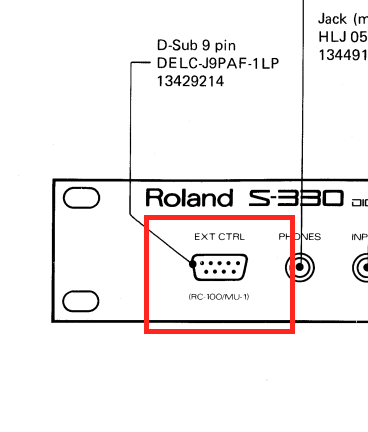
On the front panel of the sampler, you have a DB9 socket where you can plug the remote (RC100) to control the sampler parameters and menu browsing.
My objective would be to control this from the Arduino.
Would be nice to anticipate what the frequency might be, since he will have to wright the code the use it. Do we know if the clock is TTL or some odd voltage?
Since the Clock seems to be generated by the sampler, i'm not sure I need any clock rate detail.
I'm also assuming that the clock is using TTL voltage.
I'm waiting for a delivery on a "real" oscilloscope next week to start debug all of this.
(until now, I am using a 20 $ Chinese DSO kit as an oscillo, which was ok for small diy projects, but is a bit of a pain to debug multiple signal at once )