I am trying to control an Ultramotion Linear Actuator that takes in strings as commands such as TR TE TA .... etc. I have been able to get the Linear actuator to work using a USB to RS232 converter and the program PuTTY. However i need to control the Actuator with the arduino. I have not been able to get the arduino to control the Actuator so far and i have no clue what the exact problem is that I'm encountering with it. I am using a max2332 circuit breakout board in order to step up the voltage to RS232 levels. I really appreciate any help i receive on this and thank you in advance. Any suggestions as far as trouble shooting the problem or anyone with similar experiences would help greatly. I believe that it would be similar to the following example: https://www.arduino.cc/en/Tutorial/ArduinoSoftwareRS232
However this only takes one character i would need it to take multiple characters (i.e. TA10000) and it also doesn't use the USB to serial connector to take a value which it then echoes out the rx/tx to rs232. it takes a value from an rs232 connector and then outputs back through the rs232 connector. Again any help would be appreciated thank you for your time in advance.
TLDR;
I need an arduino to take in a string from the USB to serial connector and then output the string using rx/tx to RS232 to a servo
Have a look at the software serial library
Also look at the serial input basics - updated thread.
I have looked at both my trouble seems to be the actual sending of the string that i am receiving from the serial monitor through the rx/tx to the servo. I know that the arduino is receiving the characters since it is echoing them back to the serial monitor. When i use something like PuTTY i am able to send the string to the servo it accepts it and does what i tell it to do. When i try to send the string (I dont know if it is actually sending it) with the serial pins in my case rx = 6 tx = 7 on my uno that i send through the serial monitor via the USB to serial cable is where I believe the problem is arising.
Can you show your sketch? Can you provide a link where we can find the protocol (the TR, TE etc).
Unfortunately Ultramotion has no links to any of their documentation i can create a list of the commands, but i dont believe that will help in this case. Here is my current sketch:
#include <SoftwareSerial.h>

#define rxPin 6
#define txPin 7

// set up a new serial port
SoftwareSerial mySerial =  SoftwareSerial(rxPin, txPin);
// Specifies max number of characters (for serial monitor)
const byte numChars = 32;
// an array to store the received data (for serial monitor)
char receivedChars[numChars];

boolean newData = false;
void setup()  {
  // define pin modes for tx, rx:
  pinMode(rxPin, INPUT);
  pinMode(txPin, OUTPUT);
  // set the data rate for the SoftwareSerial port to Servo
  mySerial.begin(115200);
  //set the data rate for SoftwareSerial port to Arduino
  Serial.begin(115200);
  while (!Serial) {
    ; // wait for serial port to connect. Needed for native USB port only
  }
  // Sends to Serial Monitor to let me know program started
  Serial.print("Let's Get Started");
  // Set Servo Speed
  mySerial.println("SP1200000");
  //Set Servo Position
  mySerial.println("AC3000");
}

void loop() {
    recvWithStartEndMarkers();
    showNewData();
    showNewData1();
}

void recvWithStartEndMarkers() {
    static boolean recvInProgress = false;
    static byte ndx = 0;
    char startMarker = '<';
    char endMarker = '>';
    char rc;

    while (Serial.available() > 0 && newData == false) {
        rc = Serial.read();

        if (recvInProgress == true) {
            if (rc != endMarker) {
                receivedChars[ndx] = rc;
                ndx++;
                if (ndx >= numChars) {
                    ndx = numChars - 1;
                }
            }
            else {
                receivedChars[ndx] = '\0'; // terminate the string
                recvInProgress = false;
                ndx = 0;
                newData = true;
            }
        }

        else if (rc == startMarker) {
            recvInProgress = true;
        }
    }
}

void showNewData() {
    if (newData == true) {
        Serial.println(receivedChars);
        newData = false;
    }
   }

void showNewData1() {
  if (newData == true) {
    mySerial.println(receivedChars);
    newData = false;
  }
}
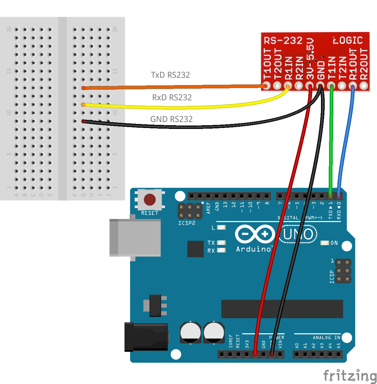
The rs232 pin out i am using is similar to this except i am using pins 6 and 7 instead of the default 1 and 0 for rx and tx:
The protocol is important as you need to know if you need a CR ('\r', 0D hex), a LF ('\n', 0A hex) or both for the actuator to accept the command.
But first things first; your code will not send to the actuator.
void loop() {
  recvWithStartEndMarkers();
  showNewData();
  showNewData1();
}
What does showNewData do?
1)
It checks the newData variable.
2)
If the newData variable is set (true), send data to the serial port (echo your command) and clears the newData flag.
Because of the underlined, showNewData1 will never be called with the newData flag being true and hence nothing is send to the actuator.
I suggest the following simple code to start
void loop()
{
  // a small buffer used for echoing
  char echoBuffer[10];


  if(Serial.available() > 0)
  {
    // read data
    char ch = Serial.read();
    // send to actuator
    mySerial.print(ch);

    // place received character in echo buffer in hex representation
    sprintf(echoBuffer, "0x%02X ", ch);
    // echo
    Serial.println(echoBuffer);
  }
}
What it does is check if there is a character; if there is,
pass it to the actuator
echo it in hex representation back to the sender
The reason for the HEX is that you can see if there is e.g. a linefeed passed in the string.
I suggest that you use putty (and not serial monitor) because you know it works. Upload your sketch first, next start putty.
Send your message as you did before you had the Arduino in between. Observe the echo, it will be something like
0x54
0x41
0x0A
0x54: T
0x41: A
0x0A: newline
You can now see what was send and the actuator should react as before.
Let us know how it goes; in the next step we can make it fancier using the serial input basics.
SoftwareSerial will not work at 115200 baud. Try 9600 baud and if that works try the next higher speed.
If you really need 115200 baud you need an Arduino with spare hardware serial ports such as a Mega, Leonardo or Micro.
...R
Ok i am trying it now if my servo has a recommended baud of 115200 will operating at 9600 still work
It did do exactly what you said with it echoing:
0x54
0x41
0x0A
However the actuator didn't respond at all. I think that this may be due to the fact that the actuator may need to take in a string instead of individual characters. I am working on finding the documentation you asked for.
The code i used is:
#include <SoftwareSerial.h>

#define rxPin 6
#define txPin 7

// set up a new serial port
SoftwareSerial mySerial =  SoftwareSerial(rxPin, txPin);

void setup()  {
  // define pin modes for tx, rx:
  pinMode(rxPin, INPUT);
  pinMode(txPin, OUTPUT);
  // set the data rate for the SoftwareSerial port to Servo
  mySerial.begin(115200);
  //set the data rate for SoftwareSerial port to Arduino
  Serial.begin(115200);
  while (!Serial) {
    ; // wait for serial port to connect. Needed for native USB port only
  }
  // Sends to Serial Monitor to let me know program started
  Serial.print("Let's Get Started");
  // Set Servo Speed
  mySerial.println("SP1200000");
  //Set Servo Position
  mySerial.println("AC3000");
}

void loop() {
    // a small buffer used for echoing
  char echoBuffer[10];


  if(Serial.available() > 0)
  {
    // read data
    char ch = Serial.read();
    // send to actuator
    mySerial.print(ch);

    // place received character in echo buffer in hex representation
    sprintf(echoBuffer, "0x%02X ", ch);
    // echo
    Serial.println(echoBuffer);
  }
}
A string is a sequence of individual characters. No difference.
You can remove the wire from pin 7 and move it to pin 2 (hardware tx). That way echoed characters will go to to both the PC and the actuator. You can use your original code but in showNewData you need to replace Serial.println by Serial.print and you need to add a line to send the newline.
void showNewData() {
    if (newData == true) {
        Serial.print(receivedChars);
        Serial.print("\n");
        newData = false;
    }
   }
(the call to) showNewData1 is now redundant and softwareserial is not used in this scenario.
This is just a quick way to see if we can get it going.
PS don't forget to set the baudrate of everything to the baudrate of the actuator.
Ok so still same results so far the echo back to the computer is working fine but nothing on the actuator side so i decided to wire up my usb to rs232 converter and stick the wires i'm using for the actuator into that to see what is going on. I tried to issue commands out of com4 and tracked the incoming data from the PuTTY window in com5 and got nothing i don't know if that helps but i thought it would be a good way to see what is actually being transmitted out of the arduino. I really appreciate all the help thank you for sticking with this problem.
Here is the code I used:
#include <SoftwareSerial.h>

#define rxPin 6
#define txPin 1

// set up a new serial port
SoftwareSerial mySerial =  SoftwareSerial(rxPin, txPin);
// Specifies max number of characters (for serial monitor)
const byte numChars = 32;
// an array to store the received data (for serial monitor)
char receivedChars[numChars];

boolean newData = false;
void setup()  {
  // define pin modes for tx, rx:
  pinMode(rxPin, INPUT);
  pinMode(txPin, OUTPUT);
  // set the data rate for the SoftwareSerial port to Servo
  mySerial.begin(115200);
  //set the data rate for SoftwareSerial port to Arduino
  Serial.begin(115200);
  while (!Serial) {
    ; // wait for serial port to connect. Needed for native USB port only
  }
  // Sends to Serial Monitor to let me know program started
  Serial.print("Let's Get Started");
  // Set Servo Speed
  mySerial.println("SP1200000");
  //Set Servo Position
  mySerial.println("AC3000");
}

void loop() {
    recvWithStartEndMarkers();
    showNewData();
    showNewData1();
}

void recvWithStartEndMarkers() {
    static boolean recvInProgress = false;
    static byte ndx = 0;
    char startMarker = '<';
    char endMarker = '>';
    char rc;

    while (Serial.available() > 0 && newData == false) {
        rc = Serial.read();

        if (recvInProgress == true) {
            if (rc != endMarker) {
                receivedChars[ndx] = rc;
                ndx++;
                if (ndx >= numChars) {
                    ndx = numChars - 1;
                }
            }
            else {
                receivedChars[ndx] = '\0'; // terminate the string
                recvInProgress = false;
                ndx = 0;
                newData = true;
            }
        }

        else if (rc == startMarker) {
            recvInProgress = true;
        }
    }
}

void showNewData() {
    if (newData == true) {
        Serial.print(receivedChars);
        Serial.print("\n");
        newData = false;
    }
   }

void showNewData1() {
  if (newData == true) {
    mySerial.println(receivedChars);
    newData = false;
  }
}
This was the example code given to me for the servo other than this not much.
int retract = 2048;
int extend = 10000;
int pos1 = 11000;
int t = 5000;//delay


void setup() {
  // put your setup code here, to run once:
  Serial.begin(115200);
  delay(t);

  Serial.println("SP1200000");
  Serial.println("AC3000");
}

void loop()
{
 positionCommand(extend);
 delay(t);

 for( int i = 0; i < 10; i++ )
 {
  positionCommand(pos1);
  delay(t);

  positionCommand(extend);
  delay(t);
 }
 positionCommand(retract);

 delay(t*4);
}

void positionCommand( int setpoint )
{
  Serial.print("TA");
  Serial.println(setpoint);
}
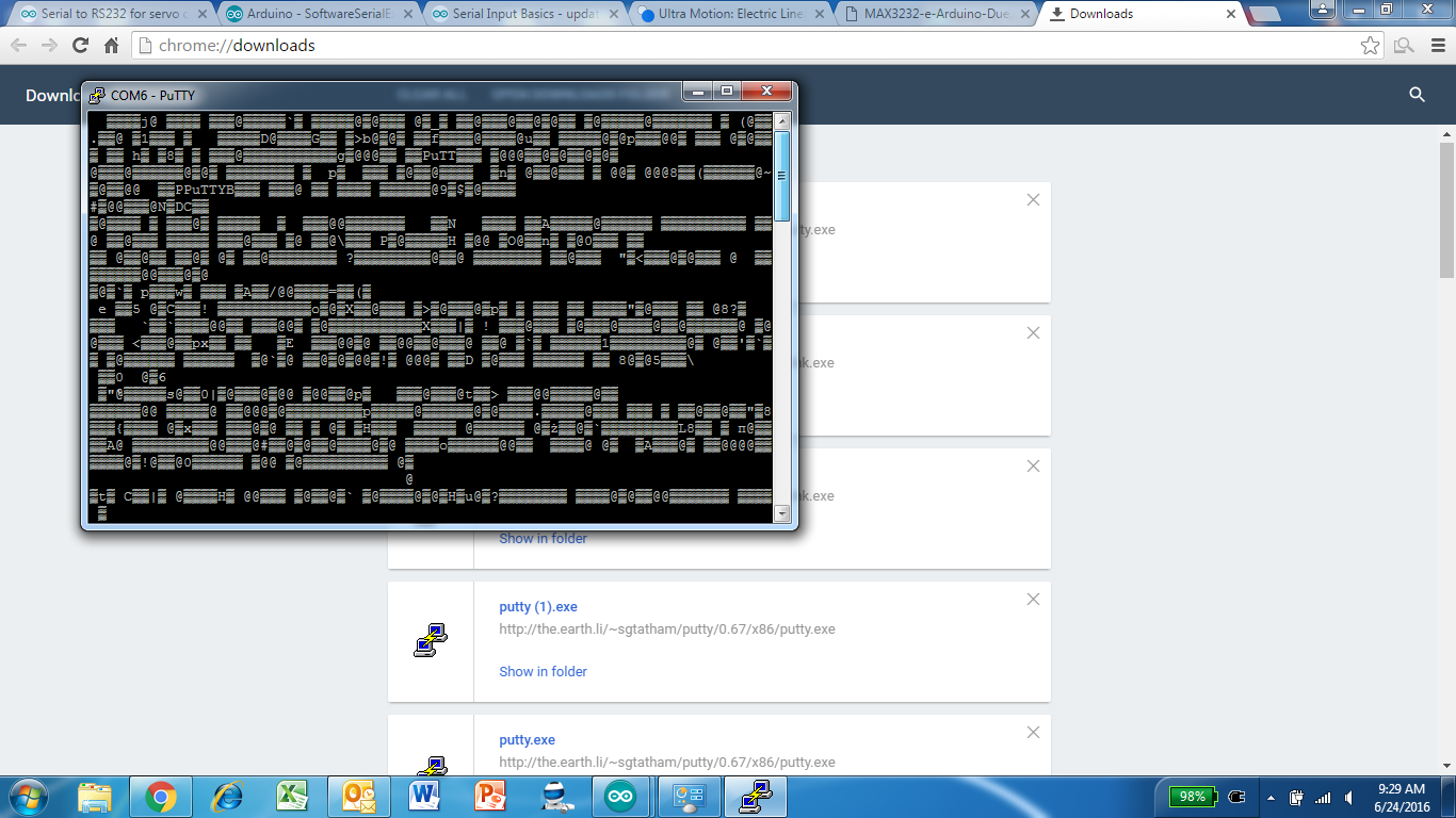
When i upload the code that the manufacturer gave me and i output it to PuTTY the following is what shows up:
The code that the manufacturer gave me did not work when uploaded to the arduino and put through the max3232 circuit that i am using to step the voltage up to rs232 levels.
Your code uses software serial on a hardware serial port and it uses hardware serial. That will never work.
Start with the below code
// Specifies max number of characters (for serial monitor)
const byte numChars = 32;
// an array to store the received data (for serial monitor)
char receivedChars[numChars];

boolean newData = false;

void setup()  {
  // Sends to Serial Monitor to let me know program started
  Serial.print("Let's Get Started");
}

void loop() {
  recvWithStartEndMarkers();
  showNewData();
}

void recvWithStartEndMarkers() {
  static boolean recvInProgress = false;
  static byte ndx = 0;
  char startMarker = '<';
  char endMarker = '>';
  char rc;

  while (Serial.available() > 0 && newData == false) {
    rc = Serial.read();

    if (recvInProgress == true) {
      if (rc != endMarker) {
        receivedChars[ndx] = rc;
        ndx++;
        if (ndx >= numChars) {
          ndx = numChars - 1;
        }
      }
      else {
        receivedChars[ndx] = '\0'; // terminate the string
        recvInProgress = false;
        ndx = 0;
        newData = true;
      }
    }

    else if (rc == startMarker) {
      recvInProgress = true;
    }
  }
}

void showNewData() {
  if (newData == true) {
    Serial.print(receivedChars);
    Serial.print("\n");
    newData = false;
  }
}
Hook pin 1 of the Arduino to T1IN of the MAX232. That way anything that is echoed to the PC via USB will also be echoed via the MAX232. You need GND as well.
Hook the MAX232 via the RS232-to-USB to the PC. Anything you type in putty connected to COM4 should show in putty connected to COM4 and in putty connected to COM5 (using the numbers you used).
Next disconnect the RS232-to-USB cable and connect the MAX232 to the actuator. If the previous test indeed showed data on COM5, the actuator should now work.
I wasn't able to get the code to echo back to either the serial monitor or PuTTY. I first tried using PuTTY for com4 (the arduino) and PuTTY for com6 (the rs232 to usb) and was unable to type anything into PuTTY which from my previous experiences tells me that it probably couldn't open the connection because that is the only time I've had that problem before. Then i tried using the arduino serial monitor instead of PuTTY and never got any values returned to the PuTTY on com6. I have the Tx pin in T1IN and the Rx pin in R1OUT just like the diagram says.
The code i used was:
// Specifies max number of characters (for serial monitor)
const byte numChars = 32;
// an array to store the received data (for serial monitor)
char receivedChars[numChars];

boolean newData = false;

void setup()  {
  // Sends to Serial Monitor to let me know program started
  Serial.print("Let's Get Started");
}

void loop() {
  recvWithStartEndMarkers();
  showNewData();
}

void recvWithStartEndMarkers() {
  static boolean recvInProgress = false;
  static byte ndx = 0;
  char startMarker = '<';
  char endMarker = '>';
  char rc;

  while (Serial.available() > 0 && newData == false) {
    rc = Serial.read();

    if (recvInProgress == true) {
      if (rc != endMarker) {
        receivedChars[ndx] = rc;
        ndx++;
        if (ndx >= numChars) {
          ndx = numChars - 1;
        }
      }
      else {
        receivedChars[ndx] = '\0'; // terminate the string
        recvInProgress = false;
        ndx = 0;
        newData = true;
      }
    }

    else if (rc == startMarker) {
      recvInProgress = true;
    }
  }
}

void showNewData() {
  if (newData == true) {
    Serial.print(receivedChars);
    Serial.print("\n");
    newData = false;
  }
}
I'm not sure if this is true but i thought you weren't able to use pin 1 and 0 while also having the serial connection open and that is why you have to emulate them with other digital pins.
Do not connect the R1OUT of the MAX232 to the pin 0. The USB converter on the board and the MAX232 will fight each other.
So one more step back now to make sure that the usual communication via USB still works. Only connect the USB on the Arduino to the PC, remove all other wires from the Arduino. Use putty or serial monitor and check if you get echoed messages (send and you should get TA back).
Working? If so,
Connect GND to the MAX232 board and Arduino pin 1 to the T1IN pin of the MAX232 board. Also connect the 5V; so it's like the picture in your reply #4 without the connection to pin 0 of the Arduino.
Connect the RS232-to-USB to MAX232 board and the PC; keep the USB between Arduino and PC as was.
Run the code again with two putty sessions; send in the putty window that is connected to the Arduino USB. Both putty windows should show TA.
You can use pin 1 (TX) as many times as you want (OK, within limitations due to maximum current); RX is trickier because the one sender might want to keep the pin HIGH while the other one wants to pull it LOW (start condition). The USB chip on the Arduino is protected by a resistor to limit the current when that happens.
It will not allow me to open both serial terminals at the same time it always takes away the arduino connection and only recognizes the USB to RS232 connection. For instance it will allow me to keep the arduino port open ill upload the code as soon as i go to hit serial monitor it immediately takes the arduino off of my devices list. I am trying to solve this problem now.
You should be able to use 2 putty sessions on different serial ports. You can also use two serial monitor sessions, but it's a bit tricky. The below works with IDE 1.6.6.
Double click your sketch (ino file) in windows explorer. This opens the IDE. Select the serial port and open serial monitor.
Double click another sketch in windows explorer (it might work with the same sketch but I have never tried that. You now have two IDEs open and they are independent. Select the other serial port in the second IDE and open serial monitor.
Sorry for the overdue reply. I couldn't get this method to work so what i did was uploaded the following code to see what i got:
void setup()  {
  // Sends to Serial Monitor to let me know program started
  Serial.print("Let's Get Started");
  Serial.begin(115200);
}

void loop() {
  showNewData();
}

void showNewData() {
    Serial.print("TA");
    Serial.print("\n");
    Serial.write("TE");
    Serial.write("\n");
    Serial.println("TR");
    Serial.println("\n");
}
This allows the arduino to keep writing the code to the serial port without me needing two windows open since i can now power the arduino via the Power Jack. After doing this test i got the following result on my PuTTY screen: (See attached image)
Im assuming this means that my circuit is actually wrong. But i am unsure I will be trying to troubleshoot further thank you for the help in advance.