Okay, its sort of a mess because its on a bread board and the servos are part of a bigger project.
I'm basically working on the electronics of a movie prop, the PKE Meter from Ghostbusters.
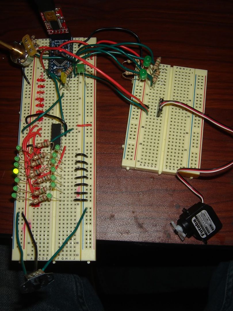
Here is the picture of my bread board prototype so far.
Just to clarify what you are seeing in the picture:
Pin 13 is being used as a 5v+ power source for:
- The Potentiometer that is wired to A0, digital pin13 and GND
- 4017 decade counter which is hooked up to Dpin7, Dpin13, and GND
- 2 resistive contact switches that are using 10k resistor, each which are also connected to digital pins 11-12 (respectively)
At any given time, there are ever only 1 LED on and the contact switches on the 5v+ coming from pin13.
There are 2 LEDs wired to blink on Dpin7 and GND
And there's a switch that is used to switch between 2 different sets of LEDs wired to the 4017 (which will be for 2 different LED displays).
Here's a video I made last night about the functionality of the electronics, for a friend to see:
Video
And lastly, here is my code so far:
#include <Servo.h>
Servo servo1; // create servo object to control servo 1
Servo servo2; // create servo object to control servo 2
const int Screendisplay = 7; // LED connected to digital pin 07
const int Screenindicator = 8; // LED connected to digital pin 08
const int winghalfLED = 11; // digital pin for the wings at half LED
const int wingfullLED = 12; // digital pin for the wings at full LED
const int pin6 = 6; // digital pin set as a 5v+ (for the servos)
const int pin13 = 13; // digital pin set as the 5v+ (for the POT, 4017, and contact switches)
int resistance1; // variable for the resistance change on the first resistive switch
int resistance2; // variable for the resistance change on the second resistive switch
int potpin = 0; // analog pin used to connect the potentiometer
int resistswitch1 = 1; // analog pin used for the resistive switch 1
int resistswitch2 = 2; // analog pin used for the resistive switch 2
int val; // variable to read the value from the analog pin
int pos1 = 0; // sets default position of servo 1
int pos2 = 0; // sets default position of servo 2
int ledState = LOW; // ledState used to set the LED
long previousMillis = 0; // will store last time LED was updated
long interval = 750;
// The setup() method runs once, when the sketch starts
void setup() {
// initialize the digital pin as an output:
pinMode(Screendisplay, OUTPUT);
pinMode(Screenindicator, OUTPUT);
pinMode(winghalfLED, OUTPUT);
pinMode(wingfullLED, OUTPUT);
pinMode(pin6, OUTPUT);
pinMode(pin13, OUTPUT);
servo1.attach(10);
servo2.attach(9);
}
// the loop() method runs over and over again,
// as long as the Arduino has power
void loop()
{
//makes pin 6 and 13 the 5v power source of the board
digitalWrite(pin6, HIGH);
digitalWrite(pin13, HIGH);
//Digital Pin 7 - 4017 decade counter for the screen display
val = analogRead(potpin); // reads the value of the potentiometer (value between 0 and 1023)
val = map(val, 0, 1023, 10, 100);
digitalWrite(Screendisplay, HIGH); // set the LED on
delay(val); // wait for the val of the pot
digitalWrite(Screendisplay, LOW); // set the LED off
delay(val); // wait for the val of the pot
//Digital Pin 8 - blinking LED
if (millis() - previousMillis > interval){
previousMillis = millis();
// if the LED is off turn it on and vice-versa:
if (ledState == LOW)
ledState = HIGH;
else
ledState = LOW;
digitalWrite(Screenindicator, ledState); // set the LED with the ledState of the variable
}
// Resistive switches and indicator LEDs
resistance1 = analogRead(resistswitch1);
if (resistance1 >= 1 && resistance2 == 0)
{
digitalWrite(winghalfLED, HIGH);
}
else
{
digitalWrite(winghalfLED, LOW);
}
resistance2 = analogRead(resistswitch2);
if (resistance2 >= 1 && resistance1 == 0)
{
digitalWrite(wingfullLED, HIGH);
}
else
{
digitalWrite(wingfullLED, LOW);
}
}