hi guys i just wanted to ask if i can connect 6 micro servo SG90R in arduino mega analog pin A0, A1, A2, A3, A4, A5. thanks <3
Yes. Use external power supply, not Arduino power.
You don't seem to have a problem with the IDE and hence your topic has been moved to a more suitable location on the forum.
The type and the size of servo is almost irrelevant.
If the servo uses a standard-RC-servo signal as input it will work.
If the signal-input of the servo expects something different than a standard RC-Servo-signal it will not work.
If you plan to supply the power for the servos from the Arduino 5V-pin this will not work.
Most servos pull too much current than the onboard-voltage-regulator can give.
Pulling too much current results in overheating the onboard-voltage-regulator and if the limit-temperature is reached the voltage-regulator will shut off.
With all microcontroller-boards you should power-supply the servos this way

If this works on the analog-pins. Give it a try and you will see if it works or not.
analog pins can be used as digital pins. The servo-library uses a timer for creating the servo-signals. It is very likely that the timer is used for invoking a timer-interrupt. If this is really the case it should work.
Only if the internal timers are used for creating "standard" PWM this works only on particular IO-pins. But a RC-servo-signal is different from a "standard" PWM.
So my conclusion is: it is very likely that it will work.
Another way of testing is taking a second microcontroller that reads in RC-signals.
Or using a 24 MHz 8 channel logic analyser (for $15)
or using an oscillosope to measure if there is a aservo-signal on the IO-pin.
or looking up the servo-library if it has comments about which IO-pins are usable
or how the signal-creation is done in detail.
I looked up the servo-library for AVR-prozessors (Arduino Uno, Arduino Mega)
static inline void handle_interrupts(timer16_Sequence_t timer, volatile uint16_t *TCNTn, volatile uint16_t* OCRnA)
{
  if( Channel[timer] < 0 )
    *TCNTn = 0; // channel set to -1 indicated that refresh interval completed so reset the timer
  else{
    if( SERVO_INDEX(timer,Channel[timer]) < ServoCount && SERVO(timer,Channel[timer]).Pin.isActive == true )
      digitalWrite( SERVO(timer,Channel[timer]).Pin.nbr,LOW); // pulse this channel low if activated
  }

  Channel[timer]++;    // increment to the next channel
  if( SERVO_INDEX(timer,Channel[timer]) < ServoCount && Channel[timer] < SERVOS_PER_TIMER) {
    *OCRnA = *TCNTn + SERVO(timer,Channel[timer]).ticks;
    if(SERVO(timer,Channel[timer]).Pin.isActive == true)     // check if activated
      digitalWrite( SERVO(timer,Channel[timer]).Pin.nbr,HIGH); // its an active channel so pulse it high
  }
The code uses
digitalWrite( SERVO(timer,Channel[timer]).Pin.nbr,LOW); // pulse this channel low if
and
digitalWrite( SERVO(timer,Channel[timer]).Pin.nbr,HIGH); // its an active channel so pulse it high
I conclude my assumption that a timer-interrupt in combination with digitalWrite() is used is correct. It should work with IO-pins A0...A5
Finally hooked up my oscilloscope and did the real test with this demo-code
/* Sweep
 by BARRAGAN <http://barraganstudio.com>
 This example code is in the public domain.

 modified 8 Nov 2013
 by Scott Fitzgerald
 https://www.arduino.cc/en/Tutorial/LibraryExamples/Sweep
*/

#include <Servo.h>

Servo myservo;  // create servo object to control a servo
// twelve servo objects can be created on most boards

int microSeconds = 0;    // variable to store the servo position

void setup() {
  myservo.attach(A5);  // attaches the servo on pin 9 to the servo object
}

void loop() {
  for (microSeconds = 500; microSeconds <= 2400; microSeconds += 1) { // goes from 0 degrees to 180 degrees
    // in steps of 1 microseconds
    myservo.writeMicroseconds(microSeconds); // tell servo to go to position in variable 'microSeconds'
    delay(5);                       // waits 15 ms for the servo to reach the position
  }
  for (microSeconds = 2400; microSeconds >= 500; microSeconds -= 1) { // goes from 180 degrees to 0 degrees
    myservo.writeMicroseconds(microSeconds);              // tell servo to go to position in variable 'pos'
    delay(5);                       // waits 15 ms for the servo to reach the position
  }
}
best regards Stefan
Referring to UNO (Fig-1), is it the VR that goes off or the auto resttable polyfuse that gets open circuited when current goes above 500 mA?

Figure-1:
@GolamMostafa assuming you have not posted a rhetorical question, I suggest you look at the schematic of a genuine UNO.
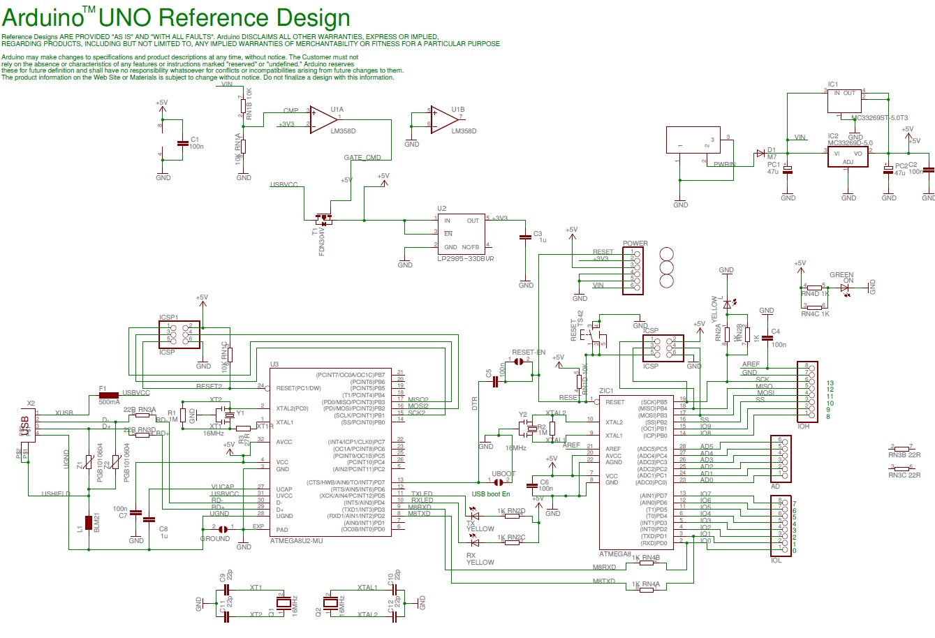
You will see that the polyfuse is only in the current path when power is being supplied by the USB port, and is intended to open in order to protect the computer which may be acting as a power supply.
Draw your own conclusion about what will happen when you supply power otherwise, and take too much off the board for servos or whatever.
a7
Right!
It was not clear to me from post #4 if power was being fed through barrel jack.