I’m seeking guidance to resolve issues with servo motor noise in sensor input.
I am aware that questions regarding this have been asked rather frequently, however, I couldn’t find an answer that made me able to solve the problem, yet, so I'd be very grateful for your help!
To give you an idea of the project: It’s a prosthetic hand, actuated with 6 servo motors, while sensors (1x EMG, 5x Hall effect) are used for control.
As soon as a servo motor moves, the sensor signals become unreadable, e.g. the max value of 1023 is held for some time, before settling back to the sensor’s baseline after the servo stops.
I tried a variety of filters (e.g. highpass, bandpass, moving average), but they couldn’t resolve this issue.
Another option I came across frequently is ‘star grounding’. However, I didn’t understand how I need to connect the GRDs since I'm quite new to this.
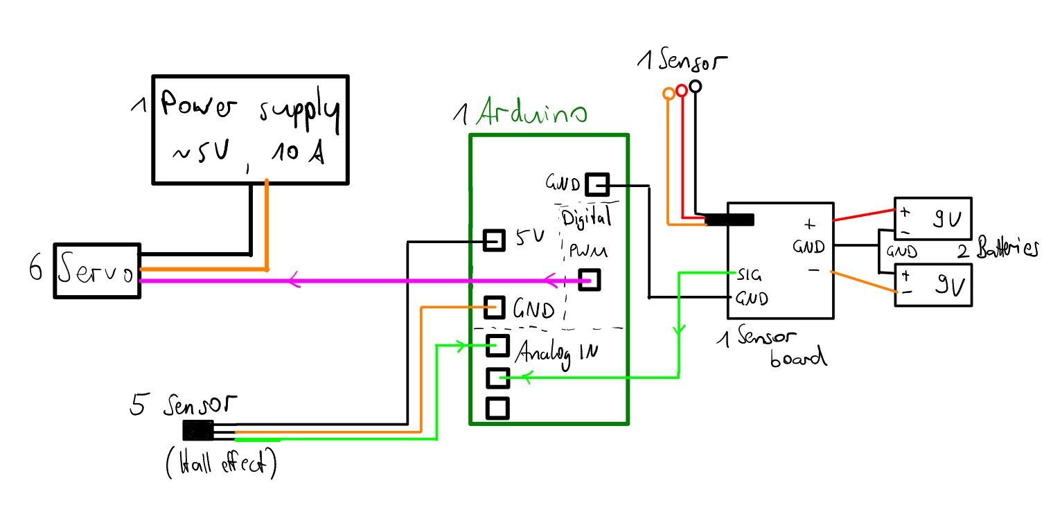
Is star grounding likely to solve my problem, and if so, can you guide me on how to do it? Here's a sketch of the circuit:
Long bundles of wires are great for radiating and picking up electrical noise.
Use shielded wire for sensor leads, route power and ground to servos separately from control and signal wires, etc. Don't power the Arduino from the servo power supply (not shown on your schematic).
If you are using the default Vcc analog reference, any noise on the power supply will be "translated" to the analog readings. Or of course, any noise in the power to the sensors.
Motors tend to create electrical noise and frequently power to the motor needs a separate power supply, or a separate voltage regulator, than the power to the "more delicate" electronics.
It's not clear from your schematic what's powering the Arduino, but if it's being powered by USB, separately from the servo power supply, that's not the problem.
Maybe give us some information on the hall effect sensors, or whatever sensors are getting noise.
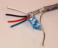
Use shielded cables for the sensors and ground the shield at only one end. Besure the sensors have clean power, motors etc will cause problems is the sensor supplies are not isolated from them. Be sure all GROUND connections are solid. This should get you started.
The first thing you need to do is remove the elastic band holding the signal wires close to the power wires; the two should be as far apart as physically possible. Next make sure that the path taken by the current to and from a device, be it sensor, motor or whatever, are as closely bound to each other as possible. Each device must have its own earth wire, not shared with any other device.
A star earth means that you have a single point where all the earths come together. If your wiring matches your schematic then it looks like you already have a star earth in that each device has a separate earth wire with them all meeting at the Arduino.
Chuck the smoke alarm batteries and fit some decent battery to drive the servos and another separate for your uC and sensors.
Aside from that, analog inputs are always in need of read 10 times and average to 0ne reading.
Use digital sensors otherwise.
Star grounding: you need to keep current-carrying grounds and sensor grounds seperate. As explained here.
You also need to use screened cable for your sensor wires. Your hall sensors are likely lower impedance so less susceptible to interference, but the EMG sensor is very sensitive.
Your diagram doesnt show 6 servo motors or how they are controlled. I dont see any power supply decoupling
Which of these cables specifically should be shielded? The SIG and GND between Arduino and the EMG sensor board, or also the ones going to the batteries?
(from link in post #4)
I don't know what you mean by 'ground the shield at only one end' and 'clean power'. Can you elaborate?
I'm using a decent power supply for the servos. Arduino is powered via USB. The 9V batteries are only for the sensor but I want to replace them anyway because they're constantly empty. Looking at the image in post#12, do you know how I could replace the 9V batteries to power the sensor?
In other words, we should use a moving average filter? I agree, I also noticed clear improvements in the signal after implementing that. But only while the servos aren't moving, otherwise as described the sensors aren't readable.
I separated the different parts as much as possible. I know that the two orange wires on the Arduino should be removed, that's a temporary solution for not having enough cables. However, the problem existed before already so that's not the main problem.
The elastic band is only holding the 6 wires to the servos together, nothing else. Then it shouldn't be a problem, right?
I thought the same, that the Arduino basically acts as star ground since all the GRDs on it are connected. Does the GRD from the 9V batteries to the sensor board also have to be connected to the other GRDs?
That's fine. I thought there were sensor wires mixed in with those.
Yes, but is it not already through one of the orange wires? Those wires are configured as a nice aerial to pick up lots of noise. They need to be physically close to each other, as per my previous reply.
Your 9V batteries are physically close to the servos and the wires to them are not bound together, but form a loop. Also, the connections to them look unreliable, I suggest proper battery clips.
I'm also concerned about the wires powering the servos because they too form loops, especially the ground wire to the Arduino. A decoupling capacitor across the power won't hurt, maybe a 0u1 ceramic and a large electrolytic, exact value unimportant, maybe 1000uF.
I'm not sure if it is possible to eliminate all noise with a circuit made up of wires plugged together like that, it's difficult enough with a carefully designed PCB.
As we figured out I already implemented the star grounding.
Can you send me an image or link of what the screened cables you have in mind look like?
Which wires specifically would you exchange for those?
The 6 servos are connected in parallel to the power supply (bottom left in image in post#15).
Their GRD is connected to the Arduino (purple cable), and they are controlled via PWM (one yellow cable for each servo).
I haven't heard of power supply decoupling yet.
Do you have a hunch about which capacitor should be used here? (The power supply delivers 4-6V and 10A.)
How should the capacitor be integrated into this circuit?
I have a 0.1 µF ceramic, but only 5x 100µF electrolytic capacitors (not a 1.000µF). Can I use one or several of these instead?
How would I connect them? Is it correct like this?
What would be the optimal solution for the right (EMG) circuit?
What would you replace the 9V batteries with (e.g. another PSU or two battery packs)?
Which wires would you use for the 2 connections to the Arduino and for the 3 to the power supply?
A shielded cable or screened cable is an electrical cable that has a common conductive layer around its conductors for electromagnetic shielding. This shield is usually covered by an outermost layer of the cable.
Yes, that is how you connect the capacitors, please make sure you get the polarity of the electrolytic capacitor correct, they don't half make a loud bang when they explode.
The exact values are unimportant. If 100μF doesn't make any difference then nor will 200μF or 1000μF or anything else. Yes, you can solder several in parallel, make the leads as short as physically possible. However, problems like you are having don't usually have a single source, so you have to attack every possibility.
Given that you want absolute minimum noise maybe use 2 banks of 4 or 6 AA or AAA batteries. Does the voltage for that board matter? I am not familiar with it.
I don't understand the question, please clarify.
With regard to the shielded cable others have suggested, you connect the shield at one end only, as the star point, so in this case at the Arduino. Do not use the shield to carry current. Use one of the other wires for the ground connection.