Hi Folks,
my first post here, I hope not to violate any rules.
I am also completely new to programming ![]()
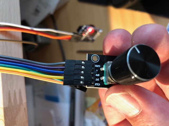
I am trying to make a beer brewing controller and am getting stuck on connecting the rotary encoder to any other PIN than I can find in posts or references online.
Tried pinMode, all sorts of available free PINs,etc. to no avail.
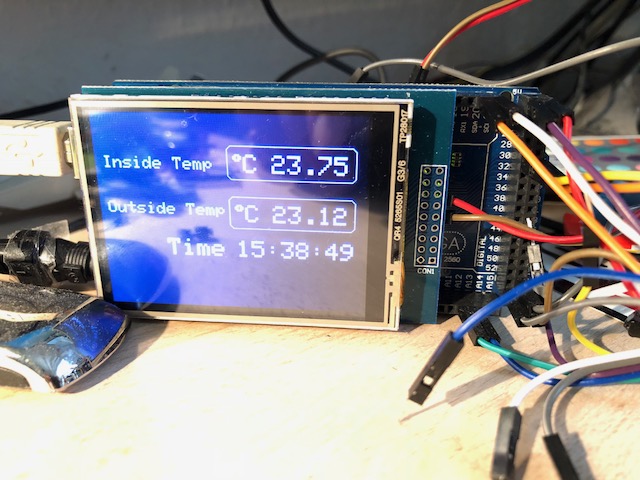
The thing is, I'm using a 2,8" TFT with shield which occupies PIN 2 and 3.
I cannot figure out how to connect the CLK and DT pins from my rotary encoder.
When I use pin 2 and 3 together with the sample code as below it works fine:
// InterruptRotator.ino - Example for the RotaryEncoder library.
// This class is implemented for use with the Arduino environment.
// Copyright (c) by Matthias Hertel, http://www.mathertel.de
// This work is licensed under a BSD style license. See Software License Agreement (BSD License)
// More information on: Arduino Projects
// -----
// 18.01.2014 created by Matthias Hertel
// -----
// This example checks the state of the rotary encoder in the loop() function.
// The current position is printed on output when changed.
// Hardware setup:
// Attach a rotary encoder with output pins to A2 and A3.
// The common contact should be attached to ground.
#include <RotaryEncoder.h>
// Setup a RoraryEncoder for pins A2 and A3:
RotaryEncoder encoder(2, 3);
void setup()
{
Serial.begin(57600);
Serial.println("SimplePollRotator example for the RotaryEncoder library.");
// You may have to modify the next 2 lines if using other pins than A2 and A3
PCICR |= (1 << PCIE1); // This enables Pin Change Interrupt 1 that covers the Analog input pins or Port C.
PCMSK1 |= (1 << PCINT10) | (1 << PCINT11); // This enables the interrupt for pin 2 and 3 of Port C.
} // setup()
// The Interrupt Service Routine for Pin Change Interrupt 1
// This routine will only be called on any signal change on A2 and A3: exactly where we need to check.
ISR(PCINT1_vect) {
encoder.tick(); // just call tick() to check the state.
}
// Read the current position of the encoder and print out when changed.
void loop()
{
static int pos = 0;
int newPos = encoder.getPosition();
if (pos != newPos) {
Serial.print(newPos);
Serial.println();
pos = newPos;
// Just to show, that long lasting procedures don't break the rotary encoder:
// When newPos is 66 the ouput will freeze, but the turned positions will be recognized even when not polled.
// The interrupt still works.
// The output is correct 6.6 seconds later.
if (newPos == 66)
delay(6600);
} // if
} // loop ()
// The End
I will add a picture of my Arduino board showing the issue with the small selection of free pins.
Connected and working are a RTC and relay board. Maybe I can use other pins for these and free up the ones for the encoder that work (only with the encoder)?
Any hint is much appreciated.
Thanks in advance!