Hello Everyone,
I am trying to figure out how to use Shift In. I am using a CD4021B chip on a Mega2560. I have everything hooked up and it appears to be 'somewhat' working. The problem is that one of my 8 buttons will not trigger a HIGH reading on the chip.
The button in question is connected to Pin 8 on the chip. When I press it, nothing happens. My byte reads "00000000". When I press the button next to it, Pin 7, my byte reads "10000001". All the rest of the buttons seem to work correctly except for the last button.
My board is wired exactly like the example on the shiftIn tutorial.
In this project, I would like to read from the shift in register and write the bits into the "masterArr" array.
My Code:
//shiftOut Pins
int outClockPin = 45;
int outLatchPin = 46;
int outDataPin = 47;
//shiftIn Pins
int inLatchPin = 42;
int inDataPin = 43;
int inClockPin = 44;

byte masterArr[8] = {0, 0, 0, 0, 0, 1, 1, 1};

// shiftIn Var
byte shiftInData = 159;

void setup() {
  Serial.begin(9600);

  //shiftOut setup
  pinMode(outClockPin, OUTPUT);
  pinMode(outLatchPin, OUTPUT);
  pinMode(outDataPin, OUTPUT);
  //shiftIn setup
  pinMode(inLatchPin, OUTPUT);
  pinMode(inClockPin, OUTPUT);
  pinMode(inDataPin, INPUT);
}

void loop() {
  getShift();
  sendShift();
  delay(2000);
}

void sendShift(){
  byte alpha;
  for(int j = 0; j < 8; j++) {
    bitWrite(alpha, j, masterArr[j]);
  }
  Serial.print("out to shift = ");
  Serial.println(alpha);
  Serial.println("............................");

  digitalWrite(outLatchPin, 0);
  shiftOut(outDataPin, outClockPin, LSBFIRST, alpha);
  digitalWrite(outLatchPin, 1);
}

void getShift(){
  digitalWrite(inLatchPin,1);
  delay(20);
  digitalWrite(inLatchPin,0);

  shiftInData = shiftIn(inDataPin, inClockPin, MSBFIRST);

  for(int i = 0; i <= 7; i++){
    int x = bitRead(shiftInData, i);
    masterArr[i] = x;
    Serial.println(x);
  }


  Serial.print("in from shift = ");
  Serial.println(shiftInData, BIN);
  Serial.println("............................");
}
Thank you in advance for any help you can give!
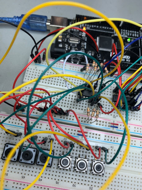
Here are some images of the wiring. I followed the example as best I could and double-checked the wiring against it a few times. Not sure how I can get better images of the wiring - it's a bit of a rat's nest...
https://drive.google.com/open?id=1C-sQMoyTAhn-6tdHQEd1XR9T1aE-wTNV
https://drive.google.com/open?id=1hXIQcsVVrokTjFoC23FhasJV_4a5VwI_
https://drive.google.com/open?id=19onCubxwpxuj0Hk0aLIWlajnBwY2Aquu