I am stuck on a problem that i thought was rather simple. I need to execute code before shutdown.
I have an ESP8266 D1 mini, that is used to display stuff on an ePaper Display. I am trying to add a switch, that turns the ESP off, but before it does, i want to "clear" the display. I tried several approaches, none of them really worked. For example, i tried to just "deep sleep" the ESP, and use the switch to trigger the reset but that didn't really work either, because that would keep reset low and therefore not boot.
So what i need: A switch that sets a GPIO pin high, so i can react to it in code and clear the display. Then i need the esp8266 to shutdown (deepsleep would be fine as well). As long as the switch stays in this position it should just stay off. Then i want the same switch, when switched back to on, to start the esp again and just run from there...
it sounds rather easy, but i cant get my head around this.
Hey thanks but no - its supposed to be exactly one sliding switch. Anyway i think ur idea has the problem, that just connecting one button to reset would not work because reset wants only a short pulse to gnd i guess?
That would have been an important point to have put in your first post. It would have prevented me from wasting my time giving an unsuitable suggestion.
The D1 mini's built-in reset button works that way, it's not a problem.
Please avoid further unsuitable suggestions by describing this switch in more detail. How many terminals does it have, for example? Is it break-before-make or make-before-break?
So i tried to wire it exactly as in the circuit u sent me, but it has some sort of issue. I thought, when the switch in ur circuit is closed, it would send a short LOW signal to reset. The way i wired it, it is the other way around. Would u assume that is correct?
I could even work with this, just configure the GPIO to turn off differently, but when i close the switch, it throws exceptions... something seems off.
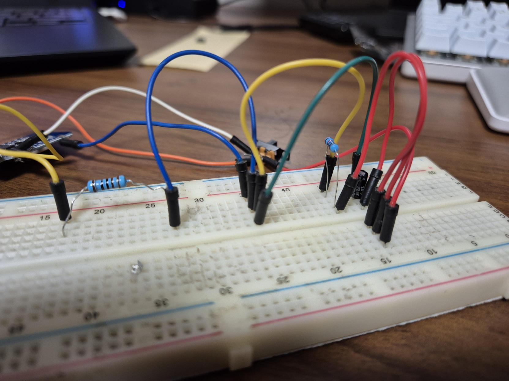
Can u help me with these imgs? Or do u need anything else?
Your breadboard may be part of the problem, most breadboard have connection issues and you have already been told about the board connections. Put hdrs on the board then insert male ends into a breadboard of a female hdr to insert the board into. Next try to replace as many breadboard connections with hdrs that have immensely better connectivity.
Ok i didn't consider connectivity could be an issue because it created a rst pulse at last. But i will double check everything and maybe solder some stuff and then come back to u
Next, minimise your use of Dupont wires, they are notoriously unreliable.
Test and then cut a couple of the Dupont wires in half and strip the cut ends. Solder these to the switch terminals. Now you can connect the switch to the breadboard reliably.
All your other Dupont cables can be replaced with solid-core connecting wires cut to length and laid flat and straight on the breadboard. Like in this example:
So the problem was not in the connectivity but i made two mistakes. First (and bigger/more confusing) mistake i made: i shorted the R of the RC Element .... that led to some weird behavior. Second mistake, i used GPIO8 as INPUT_PULLUP.
Now that i fixed both issues, it works kind of well. I just think the pulse on the RST pin is too long, because i fire multiple resets, but that should be achievable by changing the values of the RC element
EDIT: after i thought it works well, it turns out it doesn't ... the ESP needs two rst pulses everytime i want to wake it from deepSleep. After quick online research, i figured many ppl have this issue and i cant figure out how to solve it. U guys have an idea? It just needs a second reset everytime, after prompting the following error on the first reset.
Ets Jan 8 2013,rst cause:2, boot mode:(3,6)
Update: After i took a bit of a break, i tested a little more today. Turns out, the reset works fine while the ESP is operating. As long as i don't start the deepSleep, the reset will reboot the ESP. As soon as i enter deepSleep, it need two resets. And here is the weird part: this also happens when i use the ESPs own reset button. I get the same error, it just won't restart.