I have a small personal project where I would like to read with Arduino the rotation of a CPU fan. The fan is a PWM Arctic p12 Max, with 4 wires. I have successfully sped it up and down using PWM, however, I am a bit stuck when it comes to reading the SIGNAL / TACHO.
The issue is, that when I try to read the signal, the amplitude is low.
The measurements
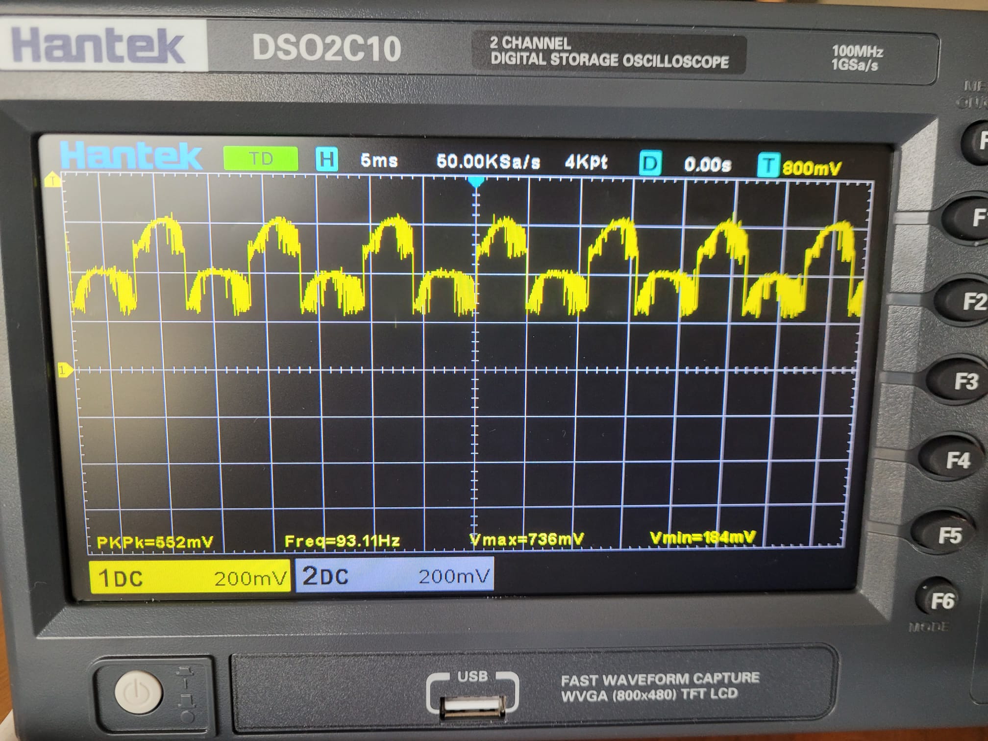
Here you can see the oscilloscope reading, in the picture below, when I try pulling up the signal to 5V (pulling up to 12 V has similar results). With either pull-up voltage, you can see the frequency is more or less what is expected for a fan that sped up to around 3000 rpm with 2 pulses per rotation, however, the amplitude is very low. Around 1 V for the 12 V pull-up and 0.5 V for the 5 V pull-up. In addition, the signal is noisy and neither low voltage is at 0 V. I was hoping to use this signal in my Arduino project, having a signal that varied from 0 to 5V, but using this signal as is makes it hard to properly measure the rpm.
The circuit consists of a USB power delivery board, set to output 12V (confirmed working with a multimeter), and a buck converter to drop the 12V to 5V (confirmed with a multimeter). The fan is powered with the 12V while the PWM is set to the 5V, to simulate 100% duty. The fan speed SIGNAL is connected to a pull-up resistor of 1K Ohm (I also tried other values from 100 to 10K Ohms) and the pull-up voltage is 5V (I also tried with 12).
Question
Do you see something wrong with my circuit or how I taking the readings?
Do you have any suggestions on how to fix my circuit and ultimately read the rpm in an Arduino. I have found many tutorials for the Arduino coding part, but they all seem to depend on a decent signal from 0 to 5 V.
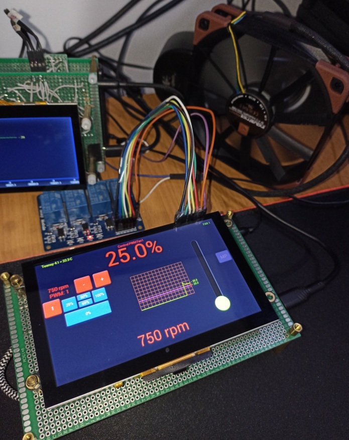
Yes, the white wire is 5V and connected to the fan PWM input and the brown wire is the fan TACH output. The Arduino is not connected in this diagram (I'll connect it later when the signal looks better). The scope ground is connected with the dark wire on the bottom left of the image. It's connected to the bottom (-) ground rail which is connected to the upper (-) ground rail, and therefore shares ground with the fan.
Just to double-check, I connected both (-) ground rails with an extra wire, the result is identical.
High performance fans require a power source that supplies a constant amperage, otherwise they will not work well. If you are going to monitor it on your PC, I suggest that the power supply be directly a 12V line from your PC supply. I have an NF-F12 industrialPPC-3000 PWM. It consumes between 3.17 and 3.6 W, I have it installed along with a relay on the 12V line, this allows the fan to be turned on and off safely, without compromising either the fan or the MCU.
The RPM depends approximately on PWM, you just have to know the lower and upper limits of fan operation. In the Noctua it goes from 750 to 3000 rpm with PWM from 1 to 255, with the map function you can obtain the approximate RPM
I have 2 fans of the same model. They both present the same issue, however, they hover around different voltage levels. The one in the photo has vmax 1.6, while the other has a vmax of 2.4. So I think it is unlikely the fan is bad (unless I broke both the same way). The fans seem to work perfectly fine responding to PWM signals, and the frequency of the TACH signal looks good and corresponds to the fan speed.
I am powering it with a USB adapter that can supply 36W at 12 V, so I think it has enough power. I do not plan to use the fan in a computer.
Regarding getting the estimated rpm via the PWM, I know this is possible, but I would like the actual measurement from the SIGNAL wire. For example, I noticed that running the fan flat down on a table at full speed runs slower than if I pick it up (due to how hard it needs to work to pull the air). I want to measure the actual speed.
Can you please post a copy of your circuit, a picture of a hand drawn circuit in jpg, png?
Hand drawn and photographed is perfectly acceptable.
Please include ALL hardware, power supplies, component names and pin labels.
Are you using scope probes in x10 mode, have you set the scope to scale for x10 probes if you are?
Have you got the scope gnd connected to the circuit gnd?
The tach output should be open drain (collector) and should be able to sink up to 5mA. So it should work with a 4.7K pull-up. The fan should run at full speed with nothing connected to the PWM input. So just for debugging purposes, try disconnecting the 5V from the PWM input
A while ago I found this note from Noctua in relation to RPM control by PWM, It wouldn't be bad if you took a look, some information could be useful to you in the project
I have taken apart and reassembled the circuit at least 3 times with 2 different breadboards. I have tested pull up resistors from 100 Ohms to 10K Ohms. The picture is from when I used 1 K. The higher the pull-up resistance I use, the "worse" the signal gets. The signal goes flat.
Do not go back and add to old posts, anything that we ask for is best put in a new post.
Imagine someone later using this thread to solve a problem they have, by editing an old post you have confused the flow of the thread.
100 ohms could burn out the transistor in the fan. 1K is the smallest you can use, but you should use something higher.
Does your fan have two connectors or just one?