These is no need to put resistors both sides of the speaker, it is a series circuit so just one will do. As your speaker is driven through a transistor the current will be able to be pushed to the maximum of the transistor which is 500mA.
As you have wired it you will only get a tiny current through the speaker because the 100K is in e current path.
The top circuit is not what the bottom circuit is.
Measuring AC current or voltage on a normal DVM at frequencies other than mains is not going to work so it is no surprise you see nothing.
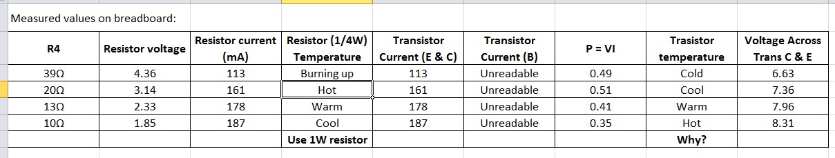
What I've done is altered R4 from the original 10R to 39R and noted voltages, current and temperatures (see below). As R4 gets smaller (and siren louder), I'm finding that the 2N2222 starts getting really hot if the siren is left on. However I thought it can deal with 400mA. Am I reading the current in the wrong location?
Ok that looks sensible.
Yes the transistor is dissipating some heat. You can calculate how much by multiplying the voltage you see between the emitter and collector when it is on by the current through the transistor.
You could add a heat sink or use a transistor with a bigger package, or in fact both. You can get clip on heat sinks for small transistors.
So heating is normal - that's good to hear. The unit is a T0-92.
Admittedly, the siren will only be on for 2 seconds every hour or so when it sounds, so in that time it doesn't heat up much at all. But I see what your hinting at with voltage x Current (P=VI). At 8.31V and 0.187A, that's 1.6W. I will use a larger transistor in the final circuit board.
So now I'm ready to add this circuit to my main project. Thanks so much for your time. Chris.
Not quite right. The voltage you need is the saturation voltage. That is the voltage across the collector / emitter when the transistor is on. This will be something in the region of 0.7 to 2.0V depending on the transistor.
You see when the transistor is off and here is a lot of voltage across it there is little or no current. When it is on there is all the current and a small voltage. That is what goes into generating the heat as you are burning off this excess power.
That is why you use a FET for higher currents. The FET has an on resistance which results in much less power burning than a transistor's saturation voltage.
Yea, I did connect the 2 grounds together. I just double checked again.
I've attached the datasheet of the 2N2222 if that helps. I'm not really sure exactly how to read it and how the figures apply.
Yes, I see where you're reading it on the data sheet. So I assume therefore the current at the base needs to be at least 400mA/40=10mA min to achieve saturation - which is within the Arduino 20mA limits.
So trying to do the calculation on the base resistor, am I correct in assuming the drop in voltage between BE (I.e. Vbe.sat) is somewhere between 1.2 and 2V according to the data sheets?
Assuming it is 1.9, then R = (2.55V - 1.9)/0.01A = 65 ohm.
If it is the typical 0.6V drop, then R = (2.55 - 0.6) / 0.01A = 195mA.
I tried both values. Measuring it with the 195R, the current was close to 10mA. With the 65R, the current was close to 20mA. The later a bit high for the Arduino.
In both cases, the current at the speaker remained around 200mA. Maybe I've got it wrong. The horn speaker may only draw 200mA???
Is there a way of checking the horn speaker? The only marking I can find is at the back where it says it's 16 ohms. It was part of a house alarm that ran on 240V. I "assumed" it is DC and typically 12V(?). Is there a way of working out its specs?
Typically this sort of thing works either off 12V or 24V. Also the 16 ohms is an impedance not a resistance. They are very similar things and both measured in ohms. But an impedance is a frequency dependent measurement and is often quoted at a specific frequency.
Is there a way of working out its specs?
Only from measurements and I suspect you do not have the equipment to do this. Your DVM will not measure AC currents an voltages unless they are 50-60 Hz and a sin wave. To measure other wave forms and frequencies you need an AC millivoltmeter. Typically looking like this:- http://www.ebay.com/itm/Rohde-Schwarz-URV-5-URV5-394-8010-02-Millivoltmeter-/252122319013
The other problem you have is that the circuit you have will only move the speaker cone from half way to out in one direction. In order to get it to move the full range, and hence sound louder you need to have AC in the speaker. This can be done by coupling the speaker to the output of a H-bridge driver with a large electrolitic capacitor.
Grumpy_Mike:
Assumptions is the mother of all cockups.
Yes, an assumption was a bit of a risk.
I agree that measuring the waveform for me is a little out of reach. I do however like the millivoltmeter!
I have to admit that the speaker (horn) I have is quite loud, even only at 200mA. I just wanted to hear the max (and be able to do the calculations too). Never mind. I now have Jurs original suggested circuit bread-boarded and working well enough.
I did a quick check online for another horn. I found one at "Radio parts". I found a suitable one (98dB) for only $10AU (LINK). However, no detail of the voltage (12 or 24), nor if it is AC or DC. Typical. I might ring them Monday as it would be good to get this right. Fingers crossed.
cjcj:
However, no detail of the voltage (12 or 24), nor if it is AC or DC. Typical.
Typically speakers are sold by "wattage" and "impedance" only.
Same as amplifiers are sold.
Output voltage is irrelevant and typically NOT specified. With speakers AND with amplifiers.
Just the input voltage for the amplifier is relevant, whether it is vor 110 volt AC mains or 230 volt AC mains or for 12 volt DC car battery or 5 volt USB (in case of very low power battery operated amplifiers).
So the only thing you have to look about is, that wattage and impedance are matching, and that the amplifier input power matches the power source you want to use (mains voltage or DC battery/adapter).
The only case where voltage is specified is with "100 Volt systems". And in that case you just have to watch out that you need to combine a "100 volt system speaker" with a "100 volt system amplifier".
If the wattage of the amplifier is higher than the wattage of the speaker, you must be careful to use the amplifier only with reduced volume setting. At full volume you might destroy the speaker.
And if the wattage of the amplifier is lower than the wattage of the speaker, you possibly will not reach the full volume with the speaker.
Thanks Jurs. I think in the end I'll just stick with what I've got for now as it works and nothing seems to be overheating or straining and the dB is sufficient. Ta.