I've tried wiring the circuit again, getting some broken numbers coming up. Wondering if its the brand of my cathode leds. I have attached the ones I have. Would that make a difference.
Thanks
I've tried wiring the circuit again, getting some broken numbers coming up. Wondering if its the brand of my cathode leds. I have attached the ones I have. Would that make a difference.
Thanks
Unlikely. If segments never light up they might be miswired or broken. If they come and go
Very random
your wiring may be dodgy or insecure. Can you get things to happen just by wiggling or light shaking?
Any tricks to assembling the circuit[?]
You may have a low quaility or worn out breadboard. You might be using the wrong wire gauge - wires should need just a bit of convincing to go into the holes. Too loose means intermittent connections. Too tight will work until it doesn't, when you've deformed the spring-like receptacle and it no longer grips very well.
If you are inserting components with small or or large lead wire gauge, or things that just don't fit at all, solder wires onto them and use those to plug in.
If you are sure of your schematic, a better way to connect things would be to get a prototype board, either a pad-per-hole type or one that mimics the layout of you breadboard. These are inexpensive.
Everything points to a mechanical issue with your wiring. Until the circuit does the same thing every time, it is a waste to work on the software.
HTH
a7
Have you tried working up your circuit on wokwi? the seven segment display there is configurable for CC or CA.
Thank you. I’ve got new breadboards. I’ve even tested many of the wires and also the breadboards . Couldn’t find any bad connections. I get some segments lighting up so I might get a simple setup with 1 display and 1 button.
Cheers.
I might try a basic tutorial on 1 display unit with 1 button. Haven’t used woki to design anything yet. Cheers.
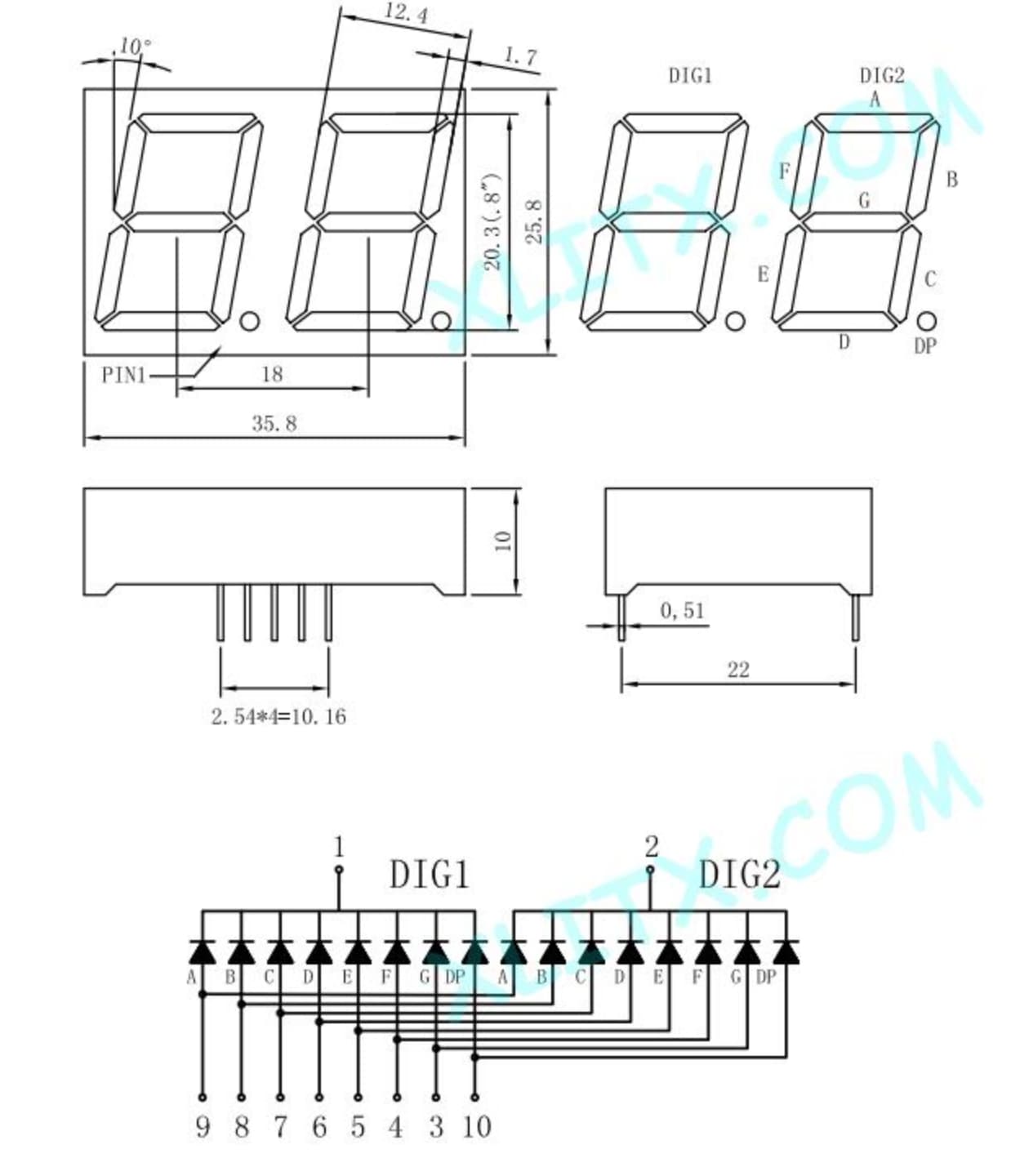
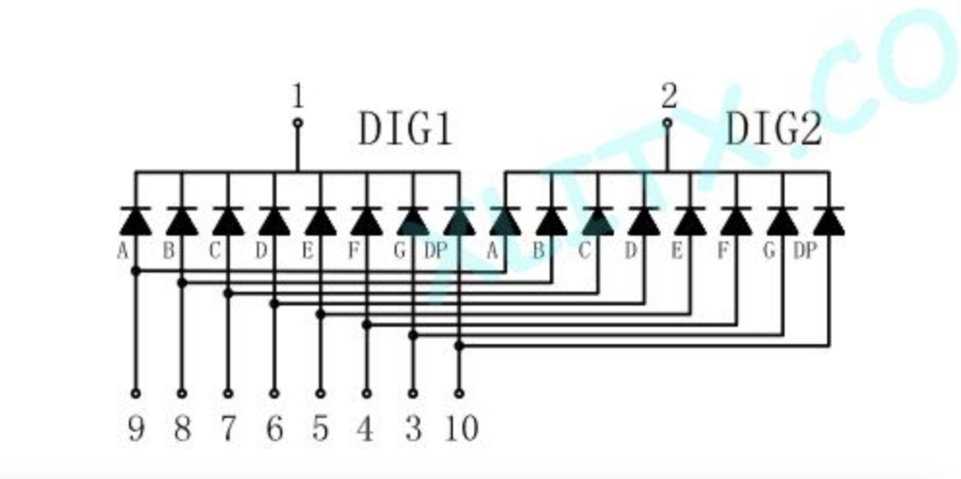
This is the 2 digit 7 segment cathode that i have. Are these pins in a standard position? Maybe they are different to the ones used in the woki simulation. All of the segments work so not faulty. Any thoughts?
Use your best common sense or a data sheet to eliminate all questions around what's hooked up to where.
I'm unaware of any standard position. You have a common anode or cathode, and you have eight pins for segments A..F and the decimal point.
Segment A..F is about the only standard here, the segments are labeled consistently.
Do you no longer experience inconsistent behaviour we've laid off against dodgy wiring or components or the breadboard?have you built your project in the wokwi? You can switch between common anode and common cathode when the display is select in the diagram pane.
Until in either simulation or real life you achieve solid functioning, it makes no sense to look at the software.
Start with the wokwi.At least there your problem will be 99.44 percent software.
a7
Finally worked out the issue. The pins on my 7 segment are in different locations to the one in wokwi. I have a diagram that I use to make sure its connected to the right pins. Probably a rookie mistake. Just have to check the wiring as both leds flash when they change. Can anyone suggest how to add a reset button to bring back to zero. I now also need to change out the 2 buttons for ir sensors. Getting there. Cheers.
Actually any reason why I don’t just setup a total reset rather doing in the code.
Thanks.
If it suits you, there's no real objection. But for your future, being able to add functionality without resorting to what is essentially turning it off, then back on again (albeit rapidly) will be a good thing to have learned.
Whenever you are ready. I haven't yet looked at your wokwi, I'm in transit and it isn't work too well on my current information appliance. L8R.
a7
Thanks for that. Ideally would prefer to put it in the code. Will work on that.
Cheers.
I just scrolled back to remember myself your project, it's been a minute.
You should keep in mind the points I made in #9 and not be surprised if it works when you use your hand or finger to block the beam, but not so well when it's actual slot cars zipping past the sensors.
a7
Yes I must do a test with the cars. The sensors pick up fast movements of my finger. I may try the idea of putting the transmitter and receiver either side of the car, and have the beam broken to trip the sensor. Some testing ahead.
Cheers.
Some success! Now have the 2 2digit lap counters working with the 2 buttons. Both count up from 0, have a reset button that resets the uno, which takes counters back to 0. Very happy with that. Only slight issue is that when one button is press both led displays flicker, or turn off for a split second. Is there a fix for this?
Cheers.
Someone said
Please read post #9. to see the effect magnified, temporarily make those 30 millisecond delays something fat like 100 milliseconds.
Basing the button handling timing on delay() is a problem you don't need to have.
It may be that your sensors don't even bounce, but you can just do the debouncing without delay() and solve a problem you might not even have.
a7
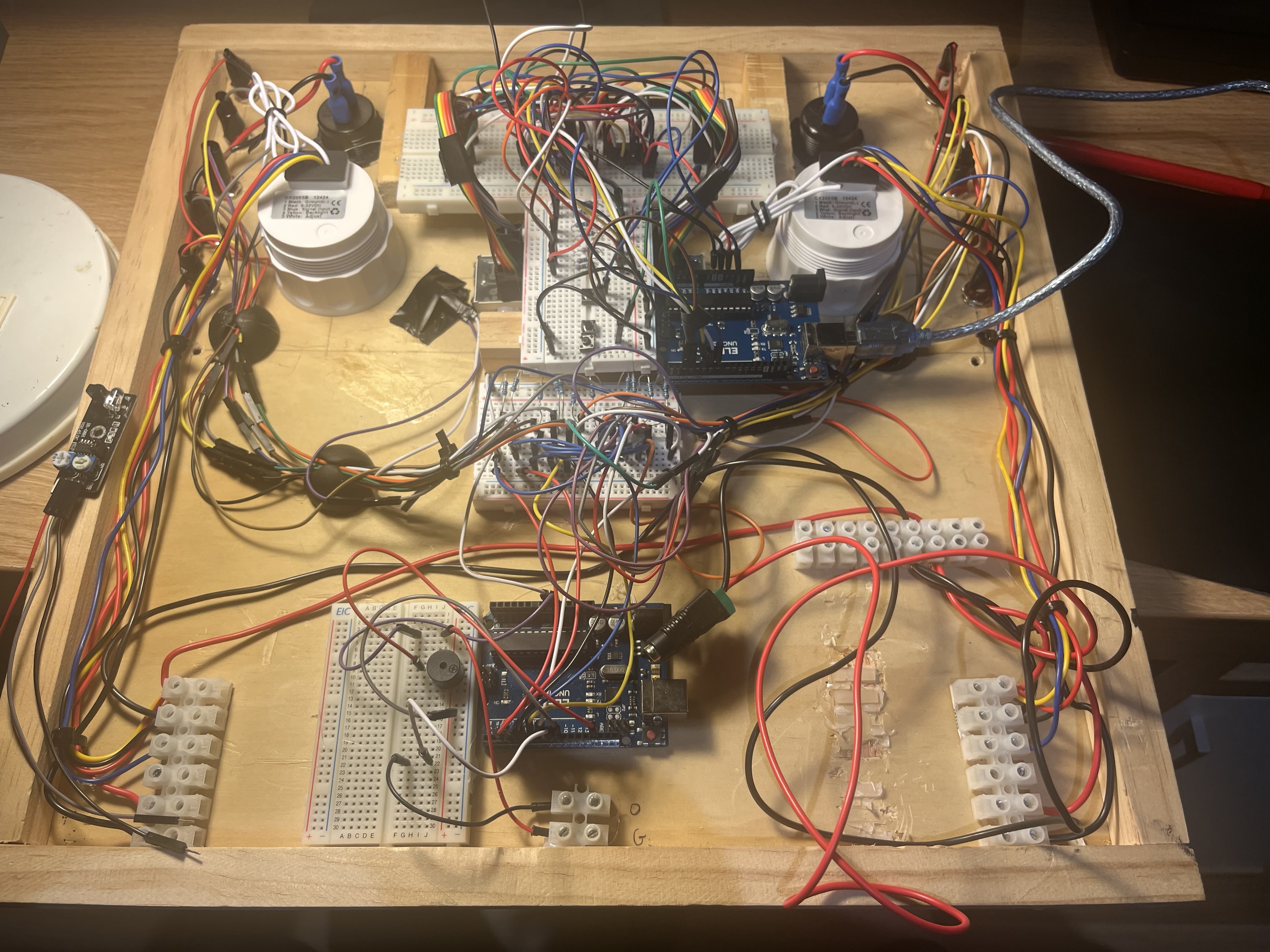
My last challenge is to replace the 2 buttons with 2 ir sensors. I have the sensors working but not integrated with the lap counters. I’ve tried putting in some code but best I can do is make the zeros blink not start counting. I don’t want to play around too much in case I lose what I have completed. Could I please have some help adding in the code to replace the button code with the sensor code. I will keep the reset button. Photo attached of the back. It’s getting a bit tight. My current sketch is at #27.
Cheers.
Write a simple test program for the sensor. It will produce the same signal as a button.
A button press yields low - high - low, or just the opposite.
A sensor yields low - high - low as a car passes, or just the opposite.
It's hard to know how to help, as you can see this is conceptually dead simple.
Post or say which post has your final button pressing code.
No it isn't. And don't you want to fix the button pressing sketch first, or are you hoping the sensor version won't need dealy()?
Post a sketch that does no more make an LED go on when a car is in front of a sensor.
Combinating the two parts, or switching to another kind of input for counting is all downhill. IMO you should be able to do it without help, but we here.
a7
#27 is the sketch in wokwi I am working with. Still have the blink on the second counter. I’m ok with it, but are you saying to take out delay from the sketch. I will try to work on the ir coding to replace the button code. More learning to be done. Sorry I don’t understand what you meant by posting a sketch when the car is not setting off the sensor. Cheers.
I changed the code and the "schematic" in the simulator, adding optical sensors (LDR, it was the only one I found in the simulator), but it should act like your sensor, and I also added a reset button.
I removed the delays because they are not necessary due to the lack of bouncing.
New version:
@ruilviana has removed any need to figure this out or learn by doing.
Here
// Depending sensor use HIGH or LOW
all HIGHs and LOWs should be changed to use manifest constants for easier and trouble free changing of the sense of the sensor
// up top settle the sense issue, or fix it

# define BLOCKED  LOW  // or is it HIGH
# define UNBLOCKED HIGH // or is it LOW


// and later in the code wherever you need to, use the constants

  if (digitalRead(sns1) == UNBLOCKED) {    // Depending sensor use HIGH or LOW
And
I will assume @ruilviana is thoroughly familiar with the sensor and its behaviour in these circumstances and is sure there is no possibility of anything other than clean signals.
a7