Hi all. I am looking at building a slot car counter using 2 infra red sensors, 2 dual seven segment displays(10 pins) and 2 of 74HC595 shift register modules and a uno r3. I want the counter to be able to have a reset button. I’m happy to research the code and circuit but I haven’t found a tutorial that uses exactly these items. My question is can I achieve what I need with the hardware I have.
Thanks.
Infrared might work if the cars are warmer than the background. A magnet under each lane would also work.
No, IR sensors can do the job, I think the OP refers to "IR obstacle sensors" to detect the car presence. There are many examples around, the IR sensors are positioned vertically above the runway, usually on some kind of "bridge": when a car passes under the "bridge" it creates a pulse that Arduino can use to calculate the elapsed time.
Some similar projects can be found googling around, using either IR sensors or magnets:
2 Likes
You could search for "exactly these items" and find the links in the previous post, or you could search on the individual items and learn about each device individually. After understanding how to write code for each device, you will understand how to use the devices together.
2 Likes
Just saying but this is totally doable without an Arduino. Without any programmation at all either
1 Like
Try this code and "schematic".
In your project, instead of buttons (which I used in the simulator due to lack of a suitable sensor), to increase the count use sensors.
These can be photodiodes or LDRs.
Sensors
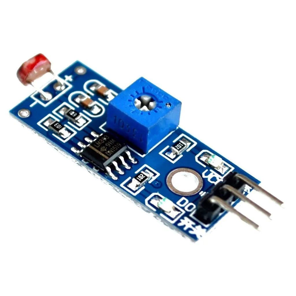
and others more
Thank you so much. This looks perfect. I’ll give it a try. Cheers.
With 2 x 74HC595 you can use up to 8 digits. (4 dual displays, or 2 quad displays).
@ruilviana's code works well with pushbuttons and will appear to work as well when you simply replace the logical element with the sensor.
The handling of the sensor signal depends on the use of delay() and while the delay is "only" 30 milliseconds, it means that in practice there will be a time where the sketch is totally blind to input.
Will that mean two nearly simultaneous triggers will be miscounted?
You can wait and see, or you can replace the dependencies with logic that does not use delay.
Since you have been handed a solution, I can hand you the fix, I suggest fixing this before it ever is seen as a problem, just so you can forget about it and sleep better.
The common patter is simple
   if it has been at long enough for any previous bouncing to have ended and
      if the signal is different to last time
         note the time of this transition and
         if the sensor is now blocked
            count another whatever up to 99
By checking the time first, we avoid delay.
wokwi tested, I only changed one of the two nearly identical code blocks. If there were three channels, I would be telling you to write a function that handles any channel. I will post the code, as wowki may be less reliable or useful for some, and code posted here will not disappear for any reason other than the disappearance of these fora.
And now that the sensors can be handled without blocking, the blocking nature of the digit scan can be accelerated. Yes, it was only 4 milliseconds total, but it needn't be. I set it at 100 microseconds, for a total of just 0.4 milliseconds, which works in the wokwi but might have to be adjusted IRL.
Observe the digits blink when you operate the delay-based channel 2. That's the effect of not updated the display for 30 milliseconds.
Any of the deleterious effects of using delay can be easily observed by making those 30 ms delays something that seriously blocks - try 500 and it will be obvious why you don't want any delay anywhere ever. Here it is a necessary evil in the digit scanning; damages are mitigated by making that very shorter.
//https://forum.arduino.cc/t/slot-car-lap-counter/1376016
/*
  SN74HC595/6  PIN Equivalente
  14 DS	   14 SER     SERIAL_IN
  13 OE	   13 OE      GND
  12 STCP	 12 RCLK    LATCH
  11 SHCP	 11 SRCLK   CLOCK
  10 MR	   10 SRCLR   +V
  9 Q7S    9 QH      SERIAL_OUT
  15 Q0  A
   1 Q1  F
   2 Q2  G
   3 Q3  E
   4 Q4  D
   5 Q5  C
   6 Q6  B
   7 Q7  DP

  # define SER 7    //data
  # define RCLK 5  // LATCH
  # define SRCLK 6  //            CLOCK
*/
int SRCLK = 6;//SHcp pin of 74HC595
int RCLK = 5;//STcp pin of 74HC595
int SER = 7;//ds pin of 74HC595
int digit1, digit2, digit3, digit4;
byte segmentsBits[] =    {B01111011, //0
                          B01100000, //1
                          B01011101, //2
                          B01110101, //3
                          B01100110, //4
                          B00110111, //5
                          B00111111, //6
                          B01100001, //7
                          B01111111, //8
                          B01110111 //9
                         };

byte score1 = 0;
byte score2 = 0;

# define sns1 2
# define sns2 3
//------------------------------------------------------------------
void setup() {
  pinMode(SRCLK, OUTPUT);
  pinMode(RCLK, OUTPUT);
  pinMode(SER, OUTPUT);
  digitalWrite(SRCLK, LOW);
  digitalWrite(RCLK, LOW);
  digitalWrite(SER, LOW);
  pinMode(sns1, INPUT_PULLUP);
  pinMode(sns2, INPUT_PULLUP);
}

# define BLOCKED LOW  // in case blocked is actually HIGH

void loop() {

  static unsigned long lastLap1Time;
//  static unsigned long lastLap2Time;

  static bool lastLap1Sense;
//  static bool lastLap2Sense;

  unsigned long now = millis();

  if (now - lastLap1Time > 30) {
    bool thisLapSense = digitalRead(sns1) == BLOCKED;    // true if seeing something passing
    if (lastLap1Sense != thisLapSense) {
      lastLap1Sense = thisLapSense;
      lastLap1Time = now;

      if (thisLapSense) {
        score1++;
        if (score1 > 99) score1 = 0;
      }
    }
  }

  if (digitalRead(sns2) == LOW) {
    delay(30);
    if (digitalRead(sns2) == LOW) {
      while (digitalRead(sns2) == LOW) {}
      score2++;
      if (score2  > 99 )score2 = 0;
    }
  }

  digit1 = score1 % 10 ; // gets dec
  showDig(digit1, 0xFD);
  digit2 = (score1 / 10) % 10 ; //gets unit
  showDig(digit2, 0xFE);
  digit3 = score2 % 10 ; //gets dec
  showDig(digit3, 0xFB);
  digit4 = (score2 / 10) % 10 ; //gets unit
  showDig(digit4, 0xF7);
}

void showDig(int digit, byte digitBits) {
  digitalWrite(RCLK, LOW);
  shiftOut(SER, SRCLK, MSBFIRST, digitBits);
  shiftOut(SER, SRCLK, MSBFIRST, segmentsBits[ digit]);
  digitalWrite(RCLK, HIGH);
  delayMicroseconds(100);
}
a7
Again for fun I ran it past chatGPT
@ruilviana’s code works admirably with pushbuttons, and at first glance, simply swapping in a sensor in place of the logical input might seem to work just as well.
However, the sensor’s signal handling relies on delay(). While the delay in question is “only” 30 milliseconds, it effectively blinds the sketch during that time—meaning it can't respond to any inputs. This poses a real risk: if two inputs arrive in quick succession, one may go uncounted.
You could wait and see if it becomes a problem—or you could proactively replace delay() with non-blocking logic. Since the core solution is already laid out, consider this an enhancement rather than a reinvention. Fix it now, and you won’t have to worry about it later—your future self will thank you.
The pattern to follow is straightforward:
if it has been long enough for any previous bouncing to have ended
    if the signal is different from last time
        note the time of this transition;

        if the sensor is now blocked
            count another whatever, up to 99;
By checking the elapsed time first, we eliminate the need for delay().
I tested this in Wokwi, modifying only one of the two nearly identical code blocks. If a third input channel existed, I’d strongly suggest refactoring this into a general-purpose function to handle all channels cleanly.
I’ll post the full code, as Wokwi links can become unreliable, and posts here tend to stick around. That way, others can benefit even if the simulation tool fades from relevance.
With non-blocking sensor handling in place, you can also tighten the digit scan routine. It was originally a 4ms block, which is modest, but still unnecessary. I brought it down to 100 microseconds per digit (0.4ms total). This tweak works in Wokwi, but real-world hardware may require further tuning.
To observe the impact of blocking code, try changing those 30ms delays to 500ms—your display will freeze, and inputs will lag or get lost. That’s a stark reminder: avoid delay() wherever possible. In the digit scanning case, it’s a calculated compromise—one that’s been minimized to reduce its footprint.
TBC the prompt was my post in its entirety with a request for an "inimitable rewrite".
a7
@alto777, I only used delay(30), because in the simulator I used buttons, (which generate bouncing).
If IR or LDR sensors are used, the delay is unnecessary, because they do not generate bouncing.
Thank you for the update. Would you mind giving me the link for the one with 2 buttons. I’ve started working on that one to see if I can get it working.
Cheers.
2 Buttons 4 Displays
"Wokwi - Online ESP32, STM32, Arduino Simulator
4 buttons 8 Displays
"Wokwi - Online ESP32, STM32, Arduino Simulator
@ruilviana - I understand. So the sketch needs more than just swapping in the alternate input hardware.
And the 1 millisecond per digit has to go, even more so in the case of four channels. You can cut the time down since nothing is blocking, or you could write the scanning using a non-blocking algorithm.
Which I recommend. Has anyone figured out how long a slot car can be expected to block a sensor? Any period of blindness makes missing a car more probable.
In @ruilviana's pushbutton code, parking in front of the sensor kills the display and blinds the sketch as far as other cars is concerned.
I wonder how long it would take Timmy to figure out that when he's in the lead, parking in front of the sensor and allowing Tommy's car to pass before resuming would put him (Timmy) up a full lap… I would bet in the course of one morning's play.
And with four cars, it's time to stop copy/paste/editing code to grow it.
a7
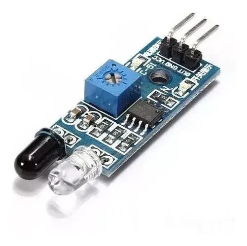
I read on one of the posts that you can set up the ir sensor to be on all the time and the car breaks the beam to count the lap. Do you think this might be a better option. Cheers.
I think you will have to plan on doing some testing. My first reaction to your question was "how else?".
Maybe you want to bounce the IR output off the passing car and sense the presence or absence of the reflection.
I don't know if that would work; I don't know if that would work better. Breaking a beam seems less fraught.
Do you have the sensors? Post a link to any details.
a7
Here are the sensors I have. I have set them to work using my finger going past the sensor. On the post I mentioned he out the sender and the receipt either side of the car and the counter worked as the car broke the beam. Sounds like a good option.

I’ve tried assembling the 2 button option about 5 times. Took a long time to check and double check correct connections, using two breadboards. Maybe a fault in a wire or breadboard. The leds work but not all segments. Very random. Any tricks to assembling the circuit.
Thanks.
If you have 4 pin buttons like those in the Wokwi simulator, the best way to wire them up is to use the 2 pins in the diagonal corners. Either diagonal is fine. That way, you can not get it wrong if the button happens to be rotated 90 degrees. If you don't use the diagonals there is a chance that you are using 2 pins that are always connected, regardless of the button state.
Thanks for that. Tried the diagonal option. Still no good. I’ll keep at it. Thanks.