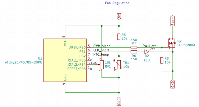
First and foremost, here’s my circuit (You can ignore most of the ATtiny pins, only what's connected to PB0 is relevant here):
So PB0 is pulsing at 31kHz and controls an FQP30N06L MOSFET (it switches a PC fan’s ground on and off to modulate its speed). The main ground will be shared with a computer’s motherboard. I’m having cold feet about noise and interference. A friend of mine told me to add a snubber network. But I don’t really understand how to make one since I’m only dealing with ground here (I don't have voltage so to say)…
Also, can I find the values for C and R without experimentation? (I’d like to make changes to my PCB before I send it to production...)
(Paulo Oliveira)
What would you do for this application?
Thanks in advance for your help.
What R and C are You thinking about? I don't see any in the diagram. I my oppinion it looks good. Maybe have a good C to support the fan positive. Kick back diodes for a fan? I would not guess that's needed.
I hope You have a mock up and You have been test running the construction?
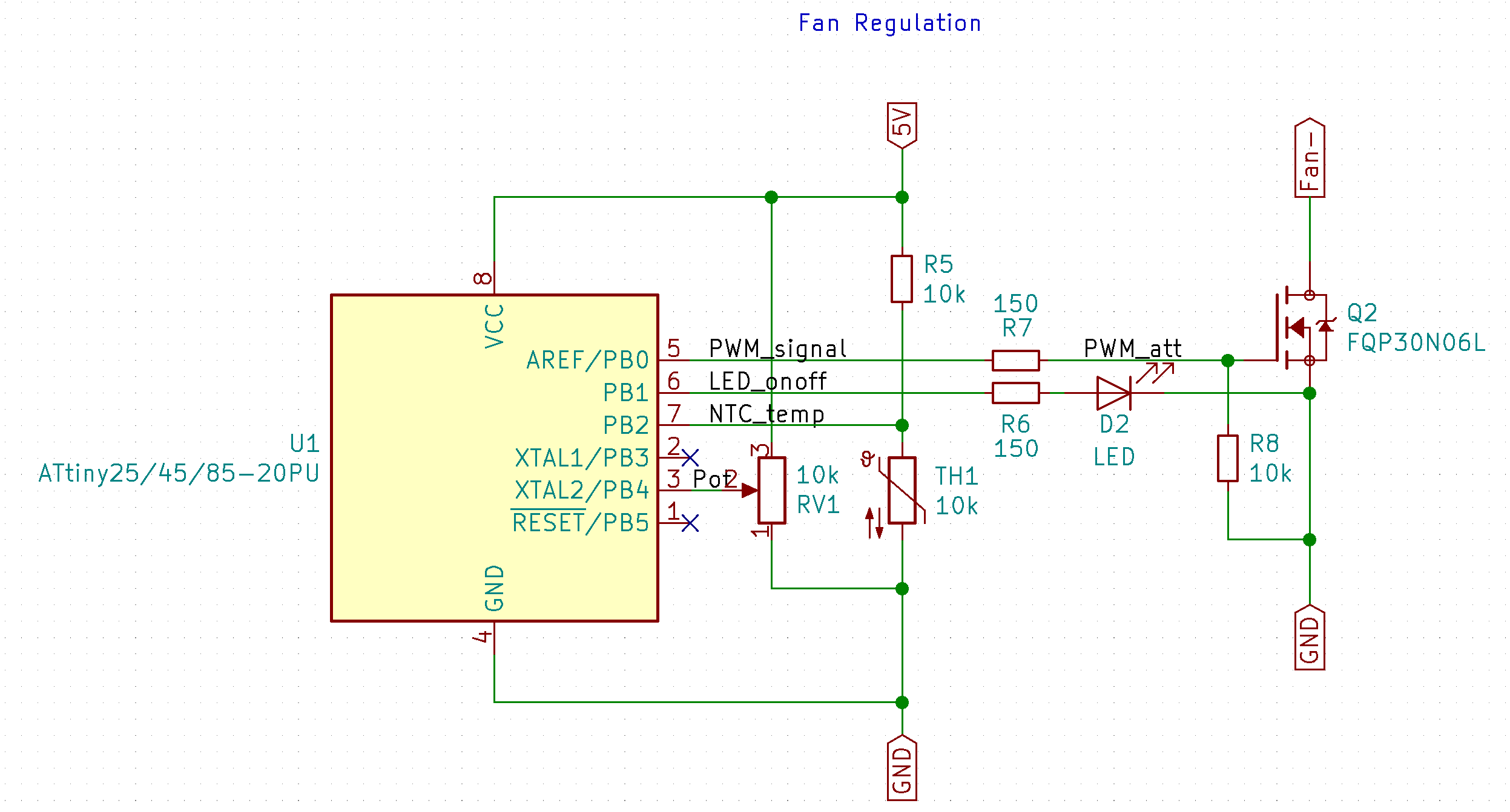
I haven't added the RC snubber to my schematic yet. The second picture is from one of those online calculators. Sorry I haven't made that quite clear. I don't know how to determine R, C and L because I'm only switching on and off GND, and according to that website: RC Snubber Calculator Spreadsheet you need to determine your frequencies with an oscilloscope, which I don't have...
I don't have any capacitor in my circuit at the moment. There is a kick back diode (1N4001) on the fan connector.
And yes, the circuit on the top has been tested extensively (albeit on its own).
Being the designer in the industry I made a construction using PWM to a 48 volt DC fan. We used a quite low frequency. Was it 25 Hz or 255 Hz? Definatly not more. The fan selling guys told it would not be possible to PWM their fan. What the hack? If You apply the voltage shortly, using Your hands and nacked wire ends the fan makes a kick run and stops.... The designed worked perfectly.
The computer/controller output as an old Darlington transistor. We did not apply any extra RC to the output.
If You hook up a DVM to the fan and spin the blades I don't think You will get any voltage from the fan.
Anyway, a kick back diode will do no harm.
The big question is how much capacitance exists in the fan's driver circuit - typically these things
have a controller chip and it has a decoupling capacitor as it should.
Trying to PWM that will create current spikes on switch on that charge the decoupling cap(s), leading
to much more interference than a simple load.
Low frequency PWM will generate much less interference. The gate resistor can then be of a high value to
reduce switching speed and eliminate interference. The pull-down resistor then needs to be moved
to the other side of the gate resistor so it doesn't drop the voltage too much.
MarkT:
The big question is how much capacitance exists in the fan's driver circuit - typically these things
have a controller chip and it has a decoupling capacitor as it should.
MarkT:
Low frequency PWM will generate much less interference.
Typical PC fans on ATX motherboards are controlled using PWM @25kHz, so how do they limit noise/interferece?
Also, how do they make their controllers work with any fan without knowing their spec?
What Mark was explaining was that you need to know what is actually in the fan, as computer fans are "brushless" and contain some electronic circuit incorporating at minimum, driver transistors an possibly Hall sensors. If they include a bypass capacitor (which is not certain) then they are not suitable for external PWM control. If they are a 4-wire type intended for PWM control, then the PWM pin modulates the internal commutating system and any bypass capacitor is outside that circuit.
The only "snubber" you should need is the reverse diode across the fan - and even that should not be necessary for a "brushless" fan as the fan electronics necessarily take this into account.
How many wires does your fan have? With 4 wires you have to find out the control line(s) and feed your PWM signal to the PWM input, that's all. With 2 wires the fan can have a simple DC motor or a DC or BLDC motor with integrated controller. The simple DC motor power can be driven by PWM with a flyback diode added, just like every other inductive load.