Solar Battery Bank Balance (Discharge 1 bank)

The question was,
I want to build a battery monitor as im having problems with the two strings balancing.

The answers were,
Change the batteries that are faulty.
Your wireing is wrong.
Rewire this way.

Good advice but not an answer to the question folks, especially based on the small amount of info available about the battery problem.

If we were working on the actual battery problem then here are some questions that should be asked.
######################################
Which string of batteries is it that are low the 0 to 12v or the 12 to 24v?
Is it the same string that goes low all the time?
Is anything else hooked on the batteries at any point?
Have you disconnected the posatives from all the batteries, waited several hours and checked the 'At Rest' voltage of each? How many were low?
Are you able to check the cells with a hydrometer? Are they all the same?
Have you followed the charging instructions on the batteries?
######################################

The only way to really know what is going on with the batteries is to treat each battery individualy, running a charge and discharge on each to find its capacity then checking all your connections for good conductivity if you find all batteries are OK.

Daz

Daz1712:
Good advice but not an answer to the question folks,

You have not attempted to answer the question either - for very good reasons IMHO.

...R

If batteries of a bank are wired as two in series, then voltage between the two could give some info about which one of the two is in a worse state.
Example: If the whole bank drops to 24volt, and all the mid-voltages are ~12volt, then there is no ballancing problem.
If one mid-voltage of the bank shows 11.5volt or 12.5volt, then there is something wrong with that set.
This is basically the same as measuring individual cells in a pack, only now with batteries of a bank.
INA219 breakout boards could be used to measure all those mid-voltages,
AND the charge/discharge currents of the sets across shunts between the two batteries.
Leo..

Answer is, don't. Just buy a premade battery monitor. Your use should have been monitored this whole time. How far were the batteries discharged? Even 'deep cycle' batteries should stick to about 50% discharge, even though they can withstand 80%, depending on battery and system. I can't even make sense of how you have your batteries hooked up. It sounds like you have series pairs of batteries that are then paralleled. What's your charging voltage? Is your system 24V?

Please explain what it is you want the Arduino to do. Because if the bank is discharging unevenly and they're connected in parallel, then there is nothing for you to do short of disconnecting the faulty bank when it gets lower than the other, and basically just run on half of your batteries and making them last half as long. And if that was your intention, you need a relay that can handle that wattage. 'Pull a load on the blah blah blah' You're going to need to spell that out because I have no idea what that bit means.

The short of it is, you are trying to fix something before you have even bothered to understand the problem. That often leads to unnecessary effort and money, which I don't think you're too eager to spend much of either.

All it may take, as a sensible first step, is to stop by an AutoZone or some such shop that offers free battery health checks. Since you have so many, tip the poor guy. Find out which battery isn't up to snuff. Then come back here and stop ignoring the advice given.

Daz1712:
Um tom, is that an Arduino? Are you running 24v direct into A1?

Daz

Not my diagram, and the OP has mentioned he/she will be using potential dividers on each of the analog inputs.
Tom... :slight_smile:

Robin2:
You have not attempted to answer the question either - for very good reasons IMHO.

...R

Have a look at #16

Daz

INTP:
Answer is, don't. Just buy a premade battery monitor. Your use should have been monitored this whole time. How far were the batteries discharged? Even 'deep cycle' batteries should stick to about 50% discharge, even though they can withstand 80%, depending on battery and system. I can't even make sense of how you have your batteries hooked up. It sounds like you have series pairs of batteries that are then paralleled. What's your charging voltage? Is your system 24V?

Please explain what it is you want the Arduino to do. Because if the bank is discharging unevenly and they're connected in parallel, then there is nothing for you to do short of disconnecting the faulty bank when it gets lower than the other, and basically just run on half of your batteries and making them last half as long. And if that was your intention, you need a relay that can handle that wattage. 'Pull a load on the blah blah blah' You're going to need to spell that out because I have no idea what that bit means.

The short of it is, you are trying to fix something before you have even bothered to understand the problem. That often leads to unnecessary effort and money, which I don't think you're too eager to spend much of either.

All it may take, as a sensible first step, is to stop by an AutoZone or some such shop that offers free battery health checks. Since you have so many, tip the poor guy. Find out which battery isn't up to snuff. Then come back here and stop ignoring the advice given.

Why not peruse the whole post. Say to #8 where the diagram is?
And #1 where he says what he wants the Arduino to do!

So in short, poster asks for how to hook up an Arduino to monitor the batteries at the mid and end point and how they go about programming it and you berate him for not reading (which you dont seem to have done) and not understanding the problem which was the reason this started.

Does not seem helpfull.

Daz

Read my post again. I ask for clarification of what he said. So, in short, I must've read it in order to be confused in the first place. Kthx move along.

Daz1712:
Have a look at #16

I did.

I could not follow it.

...R

@toxsickcity

I'm understanding your struggle.
I'm hawing the same issue with my 24V solar sistem and looking for the solution. I found of the shelf devices that do exactly what I need but they are so expensive that you can build your one for the 1/10 of the price.
I'm also understand that my batteries are on the end of there life, but this is learning proces for me and I want to convince myself that I'm wrong.

So this is what I did:

List of parts
1x Arduino Nano V3.0 - https://goo.gl/NkqSv8
1x Step Down Buck Converter - https://goo.gl/J2JNVa
1x 2-Channel Relay Module Shield - https://goo.gl/oPUoL1
1x 0.96 inch 128X64 OLED Display Module - https://goo.gl/Hunx2E
4x Halogen G4 12V - https://goo.gl/qwpbem
-- I'm using pre made voltage sensors but you can build then with these resistors;
2x 30k ohm ressistor
1x 10k ohm ressistor
2x 7.5k ohm ressistor

I'm not going to post the schematics at the time because I don't have time to do them now.
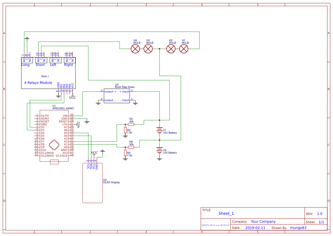
This is the code and picture of my device.

Here is the schematics , and I updated the code.

#include <Adafruit_SSD1306.h> // Display Libary


int Rl_1 = 5, Rl_2 = 6;
float dif = 0.5; // The difference between voltages as a condition for switching on the load
float v_min = 10.2;
int input_1 = A1, input_2 = A2;
int n = 20; // How many times is the average voltage measured 

float v1 = 0.00, v2 = 0.00; // volts input

float R1_1 = 29900.0, R1_2 = 40700.0; // calibrate the sensors by changing this values 
float R2_1 = 7500.0, R2_2 = 7500.0;

Adafruit_SSD1306 display(4);
 
void setup(){
   pinMode(input_1, INPUT);
   pinMode(input_2, INPUT);
   pinMode(Rl_1, OUTPUT);
   pinMode(Rl_2, OUTPUT);
   Serial.begin(9600);
   Serial.print("DC VOLTMETER");

  display.begin(SSD1306_SWITCHCAPVCC, 0x3C);
  display.display();
}

 void display_init (float vi1, float vi2){
  // Display 
  display.clearDisplay();
  display.setTextColor(WHITE);
  display.setTextSize(2);

  display.setCursor(0,0);
  display.print("B1: ");
  display.print(vi1);
  display.print("V");

  display.setCursor(0,17);
  display.print("B2: ");
  display.print(vi2);
  display.print("V");

  display.display();
  
  Serial.print("INPUT 1 V= ");
  Serial.println(vi1,2);

  Serial.print("INPUT 2 V= ");
  Serial.println(vi2,2);
  
  }

// read the value at analog inputs
float volt_1(){
  float vout_1 = 0.00, vin_1 = 0.00;
  int average_1 = 0, value_1 = 0;
  for (int i=0; i < n; i++) {
  average_1 = average_1 + analogRead(input_1);
  delay(50);
  }
  average_1 = average_1/n;

  value_1 = average_1;
  vout_1 = (value_1 * 5.0) / 1024.0; // see text
  vin_1 = vout_1 / (R2_1/(R1_1+R2_1));

  return vin_1;
  }
  
float volt_2 (float in){
  float vout_2 = 0.00, vin_2 = 0.00;
  int average_2 = 0, value_2 = 0;
  for (int i=0; i < n; i++) {
  average_2 = average_2 + analogRead(input_2);
   delay(50);
  }
  average_2 = average_2/n;
  value_2 = average_2;
  vout_2 = (value_2 * 5.00) / 1024.0; // see text
  vin_2 = vout_2 / (R2_2/(R1_2+R2_2));
  vin_2 = vin_2 - in;
    
  return vin_2;
  }

void loop(){

  v1 = volt_1();
  v2 = volt_2(v1);
   
  display_init(v1, v2); 
  
   
  // Load #1
  if (v1 - v2  > 0 & abs(v1 - v2) > dif  & v1 > v_min ) {
    while (v1 >= v2 & v1 > v_min){
      v1 = volt_1();
      v2 = volt_2(v1);
      display_init(v1, v2);
      digitalWrite(Rl_1, HIGH);
      delay(1000);
      }
    digitalWrite(Rl_1, LOW);  
    }
      
  // Load #2
  if (v1 - v2  < 0 & abs(v1 - v2) > dif & v2 > v_min ) {
    while (v1 <= v2 & v2 > v_min){
      v1 = volt_1();
      v2 = volt_2(v1);
      display_init(v1, v2);
      digitalWrite(Rl_2, HIGH);
      delay(1000);
      }
    digitalWrite(Rl_2, LOW);
    } 

delay(600);
}

The device draws 20mA of current when idelig and about 80mA when relay kick in.

munge83:
I'm olsow understand that my batteries are on the end of there life, but this is learning proces for me and I want to convince myself that I'm wrong.

This is an old and IIRC an incoherent Thread,

If you want help start a new Thread and describe your problem clearly.

...R

PS ... I suspect a circuit diagram will be essential. A photo of a simple pencil drawing will be fine. See this Simple Image Guide