hi i am doing a project for school and i have a problem, any suggestions on how i can monitor 3 batteries separately whilst they are in series, the project is battery monitoring system during charging and discharging, the aim is that when a battery is fully charged the battery would be disconnected from the pack (That part is ok as shown in the circuit) but the monitoring is being a bit difficult to achieve
any suggestions?

Show the batteries connected as well as the charger and battery discharge load.
Weedpharma
the batteries i am using are:
http://www.batterysupports.com/lg-lgdbhe21865-high-drain-2500mah-36v-20a-lithium-ion-lion-p-345.html
and i am using a programmable power supply so whilst the relays are being switched the power supply is switched off and then switched on again with less voltage to avoid over voltage and damage to the batteries that is all fine but i am really stuck on the monitoring as if i monitor seperatly whilst they are all connected it is fine but once i disconnect a battery it reads wrongly
You need to supply more information. Your circuit does not show any discharge load or method of monitoring you have tied.
You also need to supply your code.
Weedpharma
#define bat_reading 10
#define bat_reading2 10
#define bat_reading3 10

int sum = 0;                    // sum of samples taken
const int threshold = 3.01 ;
unsigned char bat_count = 0; // current sample number
unsigned char bat_count2 = 0;
unsigned char bat_count3 = 0;
float voltage1 = 0.0;            // calculated voltage
float voltage2 = 0.0;            // calculated voltage
float voltage3 = 0.0;            // calculated voltage

void setup()
{
    Serial.begin(9600);
    pinMode(7, OUTPUT);
    pinMode(8, OUTPUT);
    pinMode(9, OUTPUT);
    pinMode(10, OUTPUT);
    pinMode(11, OUTPUT);
}

void loop()
{
       while (bat_count < bat_reading)
       {
           sum += analogRead(A2) ;
        bat_count++;
        delay(100);

       }
       voltage1 = ((float)sum / (float)bat_reading * 5.015)  / 578 ;
    // send voltage for display on Serial Monitor

  if (voltage1 < 0)
       {
         Serial.println ("0 V1");
       }
       if (voltage1 > 0)
       {
         Serial.print(voltage1);
         Serial.println (" V1");
       }
    bat_count = 0;
    sum = 0;
{
  while (bat_count2 < bat_reading2)
       {
           sum += analogRead(A1) ;
        bat_count2++;
        delay(100);

       }
       voltage2 = ((float)sum / (float)bat_reading * 5.015) / 1284.29 ;
    // send voltage for display on Serial Monitor

    if (voltage2 < 0)
       {
         Serial.println ("0 V2");
       }
       if (voltage2 > 0)
       {
         Serial.print(voltage2);
         Serial.println (" V2");
       }
    bat_count2 = 0;
    sum = 0;

}

{
  while (bat_count3 < bat_reading3)
       {
           sum += analogRead(A0) ;
        bat_count3++;
        delay(100);

       }
       voltage3 = ((float)sum / (float)bat_reading * 5.015)  / 1623.52 ;

       if (voltage3 < 0)
       {
         Serial.println ("0 V3");
       }
       if (voltage3 > 0)
       {
         Serial.print(voltage3);
         Serial.println (" V3");
       }

    bat_count3 = 0;
    sum = 0;

}

}
using such a setup Redirect Notice
and for discharging for now im only using a load resistor
Modify the previous circuit so we can see how you have connected the load and charger.
Don't just say you are using a resistor as this does not tell us how it is connected. There is also no information supplied to show how you are monitoring the voltage.
"but i am really stuck on the monitoring as if i monitor seperatly whilst they are all connected it is fine but once i disconnect a battery it reads wrongly"
How are you doing this?
Weedpharma
Hi,
check your wiring around RL4.
Are you trying to charge the batteries separately and load them in series?
So that the batteries are always charged evenly?
Are the relays in your diagram ON or OFF, is ON charging, OFF on load?
Please mark pos and neg on your battery sockets to.
Tom.... ![]()
the plus and minus of the charger are connected to J8 and J9 and the resistors for now are just invented with any value and arranged through programming what would be divided by for example
voltage3 = ((float)sum / (float)bat_reading * 5.015) / 1623.52
and the previous code shows how i am trying to monitor the voltage of 3 seperate batteries hence voltage1 voltage2 and voltage3, and when i say one battery is disconnected 2 relays switch, one to remove the battery from the others and one to bypass the voltage for charging for the other batteries,
when i switch one battery out of the 3 in series the voltage reading differs for the other 2, i am asking how to control that the voltage readings would not be effected if one of the batteries are removed from the 3 batteries in series,
example when 3 in series
2.89 V1
3.99 V2
3.16 V3
when i disconnect battery 2 (voltage2)
(hence 2 are in series)
3.02 V1
2.59 V2
3.14 V3
in the diagram J1 J2 and J3 the number 1 is the positive and 2 is the negative of each battery,
and i charge the batteries in series together but monitor them seperetly, thus when charging and for example battery1 reading is 4.2V the relays RL1 and RL2 are given a pulse to switch and therefor only batteries 2 and 3 are left charging ( whilst the relays are switched the power spply is switched off and the voltage is lowered)
Hi, charging batteries in series is the worst way to charge them, as you will not be able to guarantee equal charge.
If you have provision to charge them separately and it looks like you do, then why not?
Is it safe and efficient to charge LiPo like this?
You circuit does not show how you connect the arduino to the batteries to measure the voltage.
Hi, what is your electronics, programming, arduino, hardware experience?
Tom.... ![]()
this is my first time using arduino, fro my research its ok to charge in series aslong as when the voltage of one of the batteries is reached it is disconnected ( which that part is done the hardware works properly and tested) i used to theory as shown in the image where each battery is connected to either A0 A1 and A2 and so far the resistors i invented and arranged the maths in the coding instead, which seems to be fine. but my problem is as soon as i remove a battery (by means of the relays) the voltage readings differ, do you think it could be i need to balance the batteries by means of capacitors or something?
thanks ![]()

Hi,
Sorry but, how are your batteries in your circuit connected to the arduino, we understand the potential divider.
Where on your batteries is the gnd and voltage to be measured connected.
You need to supply a COMPLETE circuit diagram including arduino, batteries and charger input.
WHY???
You have the project infront of you, we don't.
You know how it is wired, we don't.
A picture of your project would also help.
Tom.... ![]()
well that is my problem... how should i wire them to the arduino and how should the coding be done ?
so far i have tried as shown in the image and
#define bat_reading 10
#define bat_reading2 10
#define bat_reading3 10

int sum = 0;                    // sum of samples taken
const int threshold = 3.01 ;
unsigned char bat_count = 0; // current sample number
unsigned char bat_count2 = 0;
unsigned char bat_count3 = 0;
float voltage1 = 0.0;            // calculated voltage
float voltage2 = 0.0;            // calculated voltage
float voltage3 = 0.0;            // calculated voltage

void setup()
{
    Serial.begin(9600);

}

void loop()
{
       while (bat_count < bat_reading)
       {
           sum += analogRead(A2)  ;
        bat_count++;
        delay(100);

       }
       voltage1 = ((float)sum / (float)bat_reading * 5.015) /590.199  ;
    // send voltage for display on Serial Monitor

  if (voltage1 < 0)
       {
         Serial.println ("0 V1");
       }
       if (voltage1 > 0)
       {
         Serial.print(voltage1);
         Serial.println (" V1");
       }
    bat_count = 0;
    sum = 0;
{
  while (bat_count2 < bat_reading2)
       {
           sum += analogRead(A1) ;
        bat_count2++;
        delay(100);

       }
       voltage2 = ((float)sum / (float)bat_reading * 5.015) /1654.948 ;
    // send voltage for display on Serial Monitor

    if (voltage2 < 0)
       {
         Serial.println ("0 V2");
       }
       if (voltage2 > 0)
       {
         Serial.print(voltage2);
         Serial.println (" V2");
       }
    bat_count2 = 0;
    sum = 0;

}

{
  while (bat_count3 < bat_reading3)
       {
           sum += analogRead(A0) ;
        bat_count3++;
        delay(100);

       }
       voltage3 = ((float)sum / (float)bat_reading * 5.015) / 1649.62701 ;

       if (voltage3 < 0)
       {
         Serial.println ("0 V3");
       }
       if (voltage3 > 0)
       {
         Serial.print(voltage3);
         Serial.println (" V3");


    bat_count3 = 0;
    sum = 0;

}
}
}
but this doesnt seem to work as it just keeps on giving me the same result even if remove the wire ![]()
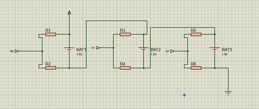
Hi,
With the way you have A0, A1 and A2.
A2 is the only one that will be correct.
A1 has the potential of Batt3 added to it, if the voltage at A1 is greater than 5V then you will damage your arduino.
A2 has the potential of Batt2 and Batt3 added to it, if the voltage at A2 is greater than 5V then you will damage your arduino.
The potential divider for each Batt1 and Batt2 HAVE to be referenced to GND, not the battery below it.
Use ohms law on the circuit you have shown and calculate the A0, A1, and A2 values.
Hi, what is your electronics and hardware experience?
Tom.... ![]()
im still at level 5 electronics, ... what you told me worked ( common ground for each) which is a step foward already, but when i disconnect battery 2,, battery 3 doesnt give any readings then (and i did arrange the wiring of relay 4)