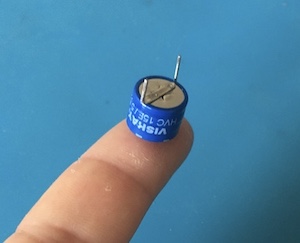
I received this nice little supercap of 15F, 5.6V and already did some tests:
This is from mouser, 8€. I had checked the size in the specs and I tough it was reading the wrong table, I expected something bigger. But it was correct
And after some weeks I have also received two other supercaps of 5F, 5.5V from Aliexpress, 2€ each.
I put the supercap in my circuit above and it charged to 5V quite fast (without load). Then I connected the ESP-12F with the buck-boost converter, disconnected the solar panel (unplug the cable) and let it run. It went from 5.01V to 4.93V in 4 hours! This was with the buck-boost converter, so I could drain it down to 2V in theory.
And the ESP-12F at the moment is programed to wake up every 30 seconds and flash the led. But the plan is to wake it up every 15 minutes, or less.
What I have found also is that it's not easy to discharge it, I tried with a 50Ω, 2W resistor but it takes long. And it has some strange effects, showing lower voltage and after a while disconnected it shows again higher voltage.
I test one the 5F supercaps quickly. It took about 15 mins to charge and went from 5.01V to 4.61V in 38 mins. I have to test more.
Congratulations! You have discovered the secret that electrolytic capacitors are actually storage batteries. The large capacitance is because there is a chemical reaction going on when you charge the capacitor. The reverse reaction takes place when you discharge the capacitor.
As you noted, the voltage is very low, so there is no danger. However, the large can type capacitors that are rated for over 50 volts and other type of high voltage capacitors are ALWAYS shipped with a wire between the terminals to short out any voltage that will may be created chemically. People have been killed by not putting the wire back on the terminals when they store the capacitors.
I have done a test with the 2 supercaps of 5F, taking sensor samples every 15 mins and sending them via WIFI once per hour. With the supercaps charged to 5V and without the solar panel connected the system was running for 29 hours.
When the voltage of the supercaps goes below 2.90V then they suddenly discharge to 1.90V.
I was checking the voltage directly in the supercaps with the multimeter. In the input of the ESP-12F it's always stable at 3.3V. Until the caps go below 3.3V, then the LDO just passes the current and the ESP-12F gets almost the same voltage as the supercaps.
I still have the problem that if it goes below 2.90V it is not able to recover itself with the solar panel, even in strong sun. I need to manually disconnect the jumper between the supercaps and the LDO voltage regulator.
So, could be that there is no sun for more than 30 hours (quite unlikely here), then when its sunny again it wouldn't recover itself.
I'm thinking to put there a transistor or a p-channel mosfet driven by a zener that would cut the connection below 3V, or something like that. With that disconnected it re-charges without problems, even from null. I'm not sure if that would work or could do something else to solve the problem.
Thanks! I was thinking to use a shunt voltage regulator, like the TL431, but I think that the voltage supervisor is better.
Another question, do I need some kind of power dissipation? I mean, when the supercaps are fully charged, the micro is in deep sleep and the sun is shining, could it be a problem?
I supose that it would be like the panel under the sun connected to nothing, I don't know if this could damage it after some time.
I know that this is a very small and cheap panel, but in general should that be taken that into account? Something like just a zener and a resistor would be a good idea?
Also, I think most cubesats are still powered by batteries. That's despite the fact that nighttime is only 40 minutes long and there's always full sun in daytime. That should be a perfect case for capacitors, but I suspect energy density is still the dominant factor. The discharge curve may also be a problem.
Yes, I know. I'm doing this small project just for fun and learning. These are my first circuits and schematics.
And anyway to keep this system running out in the balcony with just one cell of 8x6 cms and 2 small caps of 2€ is quite interesting. Now it last 30 hours without sun, and I have not yet implemented the 'surviving' mode and other optimizations.
Hi, I have been doing some test with a voltage supervisor, this one: TPS3839, with a cutoff voltage of 3.08V, what should be fine.
But the problem around the cutoff voltage is the same that I have from the begining, some kind of startup rippling.
I have been monitoring the voltage and I found that the capacitors have some elasticity or bouncing. When the microcrontroller starts up it has some demand peak and the voltage goes down about 0.3V for a short time, for example from 4.5V to 4.2V. And then it comes back quickly to 4.5V.
Then, when this happens around 3.3V this produces this rippling of about 0.3V up and down, and microcontroller is starting and stopping all the time draining quickly the charge and also preventing the recharge.
The hysteresis of the voltage supervisor is 31mV, but I would need 0.3V or more.
I don't know if I could solve this with a capacitor in the microcontroler side, a big one.
I have seen also and article to increase the hysteresis of voltage supervisor putting a resistor in parallel (Rh):
In my case the supervisor doesn't need neither voltage divisor nor pull up resistor. I'm not sure if this would work.
Actually if I can solve this rippling problem I could go as low as 2.7V to disconnet the microcontroller, and 3.2V to start it up again, using more of the capacity of the supercaps.
The capacitor would be C1, but 4.7mF instead. I haven't tried yet.
The voltage supervisor (TPS3839) is in the middle, it cuts off at 3.08V. Regarding the article attached it should be posible to increase the hysteresis to 0.3V with a resistor between VDD and RESET. I don't know if this could work in this case.
No. Because when it's over 3.08V it tries to start, then the voltage goes down and the supervisor cuts off. When it's off the voltage goes up again, switchs it on, then off... it drains power and stops. Then the solar panels charges it a bit and starts the ripple again.
Yes. They are capacitors but with a soul of batteries
I have no experience using a boost converter with a solar panel. But the boost converter will try to draw three times as much current at its input as it ouputs at 5V. Then when you add to that the supercapacitor acting like a dead short, I wonder if you aren't just at the wrong place on the panel's power curve. It seems you would need the boost converter to be an MPPT device.
Well, in any case, I think you can make your added hysteresis unidirectional by adding a diode in series with the feedback resistor. So you could delay startup to something like 4V, but still shut down at 3V. But I don't know if that would help with the startup problem.
Not all supercaps, especially the smaller (10F) ones, have a low enough Ri.
I think you should at least add 470uF across the 3.3volt supply of your ESP module.
There is an Andreas Speiss Youtube about that (smoothing transmit current peaks).
He uses 1000uF, I normally use 470uF/6.3volt tantalum.
Don't worry about having the boost converter there.
10F is tiny, and charges in no time.
Leo..
Ok, thanks, I will try that. I have to check, I'm not sure how would it work.
Charging the caps with the panel and the boost maybe is not optimal but it's not a problem. With sun it charges in a few minutes without problems, once it's above the ripple area, or with the ESP-12F disconnected (unpluggin a jumper), e.g. from 1V to 5V.
Yes, I'll try that also. I also have to optimize the code to consume the minimum after a power reset, to reduce the peak, not only after wake-up.
I could try also to put a capacitor in the RESET output, to add a delay in the shutdown and restart.
You'll need to add a resistor between the 5V rail and the supervisor VDD to use feedback. Then near the supervisor's trigger level the feedback resistor would just provide positive feedback which gives you hysteresis. But if you insert a diode pointing toward the reset output, the feedback would be effective only when the voltage is rising from zero - keeping VDD lower for longer. But when the 5V rail is falling, the diode would block any feedback from affecting VDD. So in theory you could make the turnon point near 5V, but keep the turnoff point at whatever the supervisor is set to. I have to say that I have never actually done this in a circuit. But, you know, what could possibly go wrong.
Also, I don't think you need D1 - the schottky diode preventing backflow into the panel. A boost converter typically has such a diode in series in the output that should prevent such backflow.
But it doesn't work. I have tried also without the diode.
In the top rail there are now 4.5V. In VDD 3.45V, so the RESET output should be high (threshold voltage is 3.08V), but it's low, zero.
Now I realize of one problem. When the supervisor is high the voltage in the RESET pin is almost the same as the voltage in VDD. But the ESP-12F input accepts maximum 3.6V. Luckily the chip is not fried, it still works
I'll check this. Anyway with the current voltage should work.
And I'm not sure if the diode is needed, the voltage in RESET is always lower than the voltage in VDD: 0.4V when is low and VDD-04V when is high.

 This was with the buck-boost converter, so I could drain it down to 2V in theory.


