Isn't it possible that the switches actually connect
to the rely input whether logic or coil instead of the relay contacts ?
JCA34F:
Where did you find a 2N45, your grandpa's hearing aid? Did you mean 4N45 (an opto coupler)?
It was a typo.. it's a 4N25 - optocoupler - 220V AC main ---- 100 KR --- pin 1 and 220V AC neutral --- 100 KR --- pin 2
-- this is working and so i sense if it's on or off.
what i want is to have a parallel push button to the board's push buttons, triggered by the gpio's from an ESP826612, which outputs 3V3 on high and 0V on low.
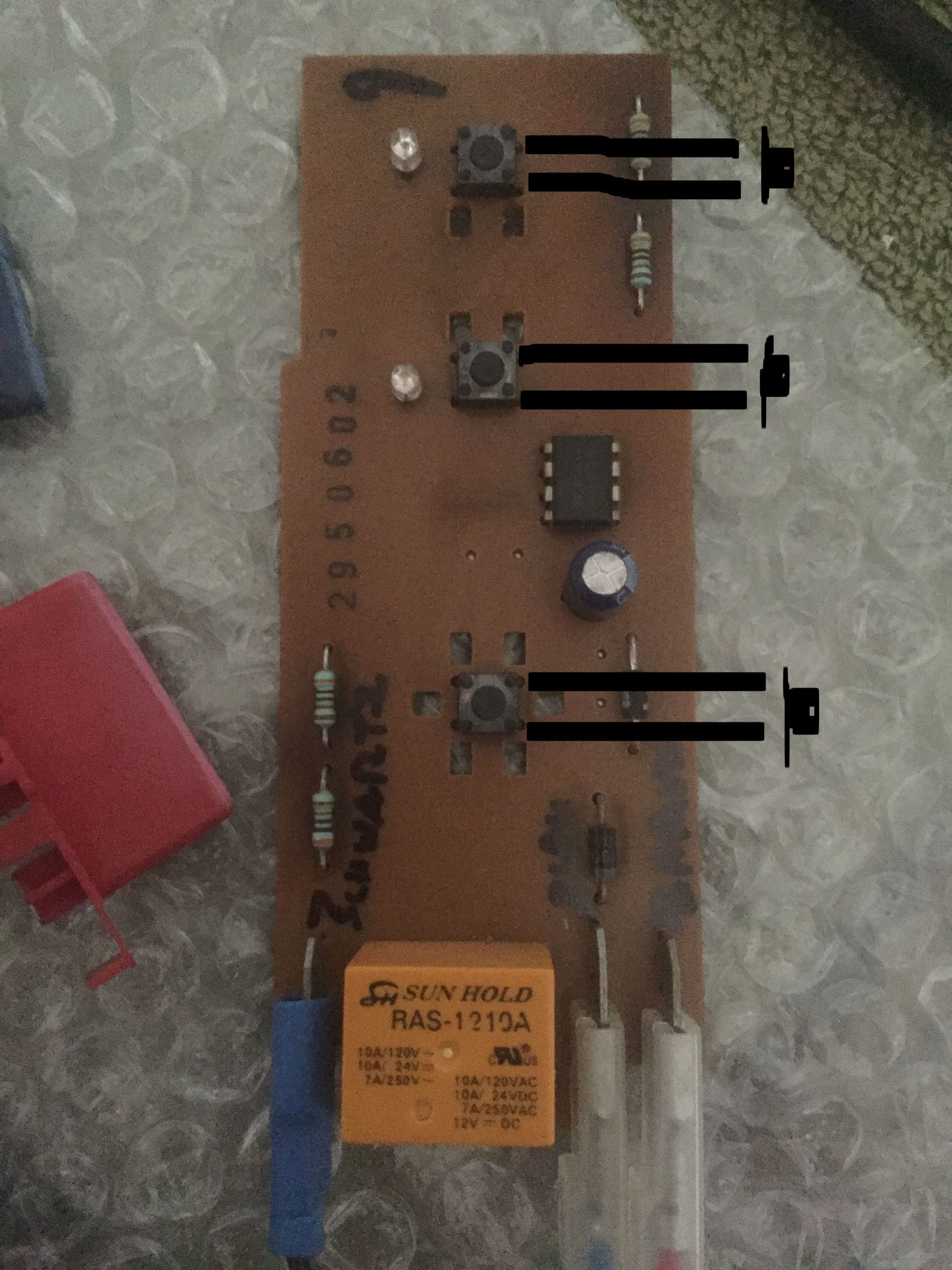
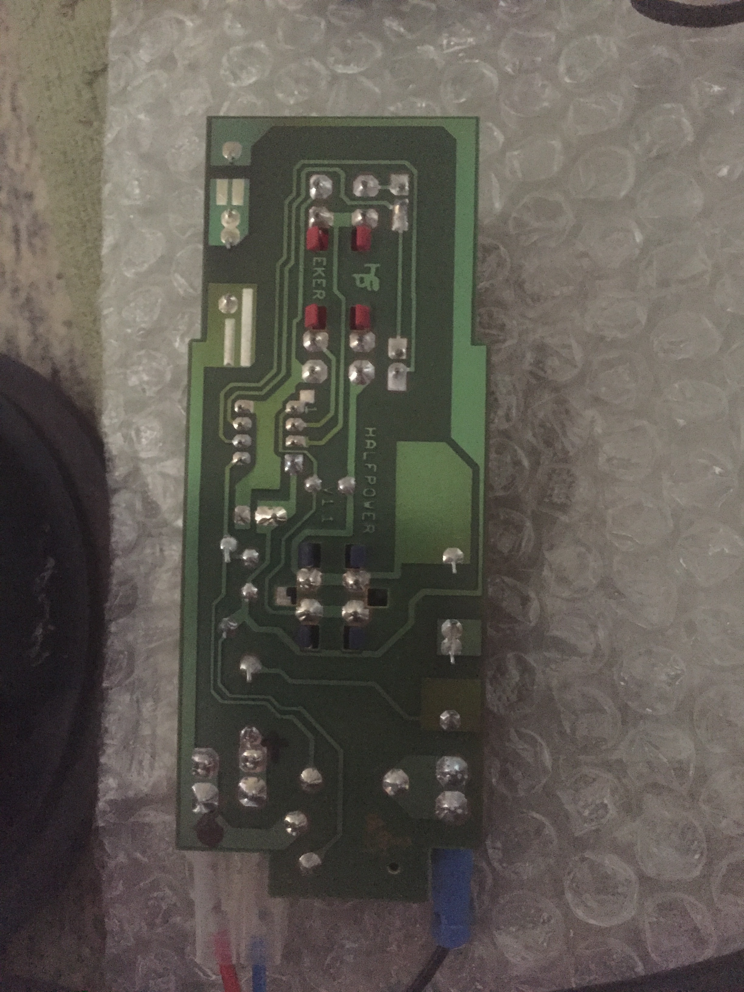
Here are the pictures of the actual board.
Where is there 220 on the boatd. Paralleling momentary pushbuttons is a common hacking practice it should be pretty straightforward. Usually it doesn't involve 220vac but worse case you can use small relays triggered by separate added pushbuttons. I wouldn't try to piggyback added circuitry that may not be compatible. I know the parallel relay contacts approach is foolproof and works every time and you don't have to worry about compatibility. I would only use a paralleled opto if I had the schematic (that Bosch won't give you) . I still believe the pushbuttons connect to relay control inputs rather than contacts but I don't know if that has been confirmed.
raschemmel:
Where is there 220 on the board.
Everywhere!
Note also the darkening of the board under the series dropper resistors. ![]()
Those are useful pictures but you should be doing the tracing, not us.
Have you actually measured the voltage across the open switches with a DMM? You can get opto isolated solid state relays in circuit board sizes, but current leakage at 220V could be a problem. Like @raschemmel said, relays will always work.
I don't see this going anywhere until the OP does a
continuity test from the switches to the relays and then from the ac input wires to the relay contacts
to see if there id continuity from the switches to the
ac or if in fact, the switches are connected to the
relay inputs or coil and not the ac. Off course it
has to be is connected from power to do this.
raschemmel:
I don't see this going anywhere until the OP does a continuity test from the switches to the relays and then from the AC input wires to the relay contacts to see if there id continuity from the switches to the AC or if in fact, the switches are connected to the relay inputs or coil and not the AC.
I really don't see the point. We know that this is a "transformerless" design and the whole board is "live". What are you trying to prove?
There is only one PCB and it has only three connections to it - Line, Neutral and Load.
Well, i decided i will go to TRIC, BT136 driven by MOC3020 (which turns to a solid state relay, without complication, being small enouth to fit the tight space with the ESP8266.
Thank you all for the comments, which educated me in the (i think) correct direction.
Paul__B:
I really don't see the point. We know that this is a "transformerless" design and the whole board is "live". What are you trying to prove?There is only one PCB and it has only three connections to it - Line, Neutral and Load.
In fact, there are the following connections:
L and N - Relay drives L to heating resistance thermostat..

By staring on the photos I traced board (=no schematic for others, it is only in my head). I am quite sure it is resistive transformerless DC power supply using half wave rectifying. Form the low voltage circuit perspective it is a constant current source.
The mysterious DIP8 IC is reading the buttons and driving both LEDs and the relay directly - without current limiting resistor for the LEDs or transistor for the relay.
The buttons simply connect pin of the IC to GND when pressed - the IC provides internal pull-ups or something like that.
The relay coil is 12V 400 Ohm (30mA; 360mW). One pin of relay coil is connected to Vcc while the other to the chip pin. It means the DC output from the power supply is at least 12V, 30 mA (+ some current for LEDs).
There is no Zener diode between Vcc and GND - the IC must provide regulation somehow and it is probably able to shunt any excess current (when LEDs and realy are off).
Since the IC is directly powered from the DC power it must be some unusual device - probably some ASIC. I would like to see the markings of the chip anyway. Can you take better photo or write it here?
@OP: what is your aim? If you want to simulate button presses you should use a transistor (or optocoupler) per button. You cannot use a triac. You can also use a transistor to drive the relay.
Another option to consider is removing the IC form the circuit, connect ESP to the buttons and LEDs and drive the relay using a transistor as you wish. Of course if the ESP fails for some reason you won't be able to operate the machine.
Smajdalf:
By staring on the photos I traced board (=no schematic for others, it is only in my head). I am quite sure it is resistive transformerless DC power supply using half wave rectifying. Form the low voltage circuit perspective it is a constant current source.
The mysterious DIP8 IC is reading the buttons and driving both LEDs and the relay directly - without current limiting resistor for the LEDs or transistor for the relay.
The buttons simply connect pin of the IC to GND when pressed - the IC provides internal pull-ups or something like that.
The relay coil is 12V 400 Ohm (30mA; 360mW). One pin of relay coil is connected to Vcc while the other to the chip pin. It means the DC output from the power supply is at least 12V, 30 mA (+ some current for LEDs).
There is no Zener diode between Vcc and GND - the IC must provide regulation somehow and it is probably able to shunt any excess current (when LEDs and realy are off).
Since the IC is directly powered from the DC power it must be some unusual device - probably some ASIC. I would like to see the markings of the chip anyway. Can you take better photo or write it here?@OP: what is your aim? If you want to simulate button presses you should use a transistor (or optocoupler) per button. You cannot use a triac. You can also use a transistor to drive the relay.
Another option to consider is removing the IC form the circuit, connect ESP to the buttons and LEDs and drive the relay using a transistor as you wish. Of course if the ESP fails for some reason you won't be able to operate the machine.
I tried to get the schema from Siemens, but they denied. As i'm total beginner in electronics, i could not find the way other than learn and ask, to educate myself.
The chip is a mlx26207ca DIP8, for which i didn't find the datasheet to be able to find out what it does perform.
I aim to make the coffee machine controleable by my homeassistant, my phone and also get the notification when is done, by wifi, using an ESP8266-12, with ESPEasy or Tasmota. But i also want to have it as standard. BEst of both worlds ![]()
Yes, i also find out the relay is a 12VDC driven coil, but as i told, i'm a beginner and i don't want fry it.
By staring on the photos I traced board (=no schematic for others, it is only in my head). I am quite sure it is resistive transformerless DC power supply using half wave rectifying. Form the low voltage circuit perspective it is a constant current source.
The mysterious DIP8 IC is reading the buttons and driving both LEDs and the relay directly - without current limiting resistor for the LEDs or transistor for the relay.
The buttons simply connect pin of the IC to GND when pressed - the IC provides internal pull-ups or something like that.
The relay coil is 12V 400 Ohm (30mA; 360mW). One pin of relay coil is connected to Vcc while the other to the chip pin. It means the DC output from the power supply is at least 12V, 30 mA (+ some current for LEDs).
There is no Zener diode between Vcc and GND - the IC must provide regulation somehow and it is probably able to shunt any excess current (when LEDs and realy are off).
Since the IC is directly powered from the DC power it must be some unusual device - probably some ASIC. I would like to see the markings of the chip anyway. Can you take better photo or write it here?
This confirms what I already said, which is that the buttons are NOT directly connected to 220V so the fact that there is 220V on the PCB is basically irrellevant to this whole post which is about hacking the switches, (which
are NOT connected to 220V). I stated already it was my 'guess' that the switches went to the relay inputs. I may
have been wrong there but if they are sinking opto led current then they are still isolated from 220 volts, despite
what other posters may vehemently believe. How this affects the approach to hacking the switches I don't know.
pw44:
I tried to get the schema from Siemens, but they denied. As I'm total beginner in electronics, i could not find the way other that learn and ask, to educate myself.
The chip is a mlx26207ca DIP8, for which i didn't find the datasheet to be able to find out what it does perform.
And you never will find a datasheet. From Siemens or elsewhere.
It performs the complete timing and control function, as Smajdalf has mirrored (and actually detailed ![]() ) all of my observations; the "magic" ASIC includes the (approximately) 12 V Zener, pull-ups for the three buttons, constant current drivers for the LEDs and relay switch as well as digital timers. It is not any common microcontroller by any means.
) all of my observations; the "magic" ASIC includes the (approximately) 12 V Zener, pull-ups for the three buttons, constant current drivers for the LEDs and relay switch as well as digital timers. It is not any common microcontroller by any means.
pw44:
I aim to make the coffee machine controllable by my homeassistant, my phone and also get the notification when is done, by WiFi, using an ESP8266-12, with ESPEasy or Tasmota. But i also want to have it as standard. BEst of both worlds
You are asking an incredible amount from yourself. Clearly there is nowhere enough space in the machine to include all of the additional electronics you would need to do that.
For a start, the "transformerless" power arrangement of this board is only ever sufficient to power that ASIC, nothing else. So you would require a switchmode converter to power your additional circuitry. The smallest of these are what you see as small cellphone chargers.
If you were to connect directly to the present circuit, then all of your additional components must be double-insulated; it would again be an immense design challenge to contain them in the present casing, I suspect impossible. So you might be able to incorporate just a custom opto-coupler interface board inside and bring its connections out, providing some safe isolation. The alternative of bringing out direct connections to the board requires you to provide robust (double) insulation of the cable and all your external circuitry.
To interface to the board is still tricky. You would use opto-couplers to imitate the switches. Not the Antique 4N25 series, use modern ones with decent performance and clearly not a MOC. Adding opto-couplers to sense the LEDs and relay is a trifle tricky as you must be careful about the opto-coupler LEDs requiring some extra current though (with modern ones) one or two mA is quite sufficient. The output transistors connect to an ESP (as you want WiFi) using internal pullup.
pw44:
Yes, i also find out the relay is a 12VDC driven coil, but as i told, I'm a beginner and i don't want fry it.
You would only need to actually control the relay if you intended to completely replace the function of this board; you would then need to emulate all of its operation.
raschemmel:
this whole post which is about hacking the switches, (which are NOT connected to 220V).
There appears to be some problem with semantics here. The buttons most certainly are connected to 220 V. Via a couple of resistors.
raschemmel:
but if they are sinking opto led current then they are still isolated from 220 volts, despite what other posters may vehemently believe.
If you call the resistors "isolation", then that is a very loose version of the term. I believe you are trying to express that the buttons do not have 220 V (AC or DC) across them, only about 12 V DC and are thus amenable to control by a "plain" optocoupler. That is in fact the case. ![]()
The buttons most certainly are connected to 220 V. Via a couple of resistors.
False.
It is stated here:
"The buttons simply connect pin of the IC to GND when pressed - the IC provides internal pull-ups or something like that."
It was my understanding that the buttons are not connected to 220V but are in fact sinking the ASIC current (on one side : ASIC IC pin,/ on other side : GND) so not connected to 220V. Go back and read his description. He never said one word about the buttons connecting to 220V. Quite the contrary. He said they are connected to the 12V DC GND. I can only hope that it doesn't become necessary to define what the word "connected" means. I think
we can agree it means "having continuity to".
So you are saying that having continuity to 220 V (the red wire) via 6k Ohms and either an electrolytic capacitor or a diode means that they are not "connected" to 220 V?
So if it suits you to see it that way, very well, but it seems to me that if you were to touch the button connection in operation, then you might just notice the 30 mA if you were also grounded.
I don't know where you get your information but there is no schematic and no proof that I have seen of any such connection as you describe and it was stated that they connect to DC GND. Did you not read the quote in my last post ? If you believe they connect to ac through resistors you'll have to present some proof because simply saying so doesn't make it true. I have seen no such evidence and I confess I made no effort to reverse engineer it from the photo. The person who claims to have done that clearly stated the switches are part of a DC circuit not an ac circuit. I see the red wire and the resistors but no connection between them and the switches so if that's what you believe why don't you post some proof ? I think it is obvious that without a schematic it is not sufficient to make
a claim. I happen to believe the other poster who says they connect to dc not ac.
The buttons simply connect pin of the IC to GND when pressed - the IC provides internal pull-ups or something like that
Where does it say here that the buttons connect to 220vac ? You are certainly welcome to your opinion but it is only fair that you back it up with proof.
The transformerless resistive power supply implies everything it is directly connected to the mains via some resistors. The connection in this circuit is: mains connection - 2 resistors in series - diode - GND - "12VDC" circuit - Vcc - 2 resistors - mains connection.
They're connected to dc not ac