Grumpy_Mike:
You are best pre calculating them in a look up table to make the output quicker.
Grumpy, 1st rule of programming: Don't optimize or refactor until you have a working algorithm.
In this case, that will not happen any time soon.

Grumpy_Mike:
You are best pre calculating them in a look up table to make the output quicker.
Grumpy, 1st rule of programming: Don't optimize or refactor until you have a working algorithm.
In this case, that will not happen any time soon.
StanO8:
Grumpy_Mike:
You are best pre calculating them in a look up table to make the output quicker.
Grumpy, 1st rule of programming: Don't optimize or refactor until you have a working algorithm.
2nd rule of computing - don't write the same lines over and over again - if you do you simply are not getting it.
So do you want to type in 256 entries in a look up table or do you want to write two lines of code.
In this case, that will not happen any time soon.
Why, this is a supremely simple problem which would have been solved long ago if the OP had extracted his digit.
Well I think I would try to get it work then I will try to improve everything..
Yes but you are not trying are you?
@
Grumpy_Mike I try.
I can produce a sine wave throught an DAC port.
And I can generate 3 pwm signals with variable frequency throught pwm ports..
my problem was how to connect the dac sine wave to the pwm signal...
Grumpy_Mike I try.
No you don't.
I told you how to do it in reply #13 but no you would not take it.
And I can generate 3 pwm signals with variable frequency throught pwm ports..
Yes but you do not want to do that do you. You want to generate a PWM signal with the duty cycle equal to the current sample of a sin wave.
@ Gumpy Mike
I try but I dont have any experience with arduino..
So this is my modified Fade code in order to get a PWM sine wave..
If it will work I will modify it to varii the frequency and duty cycle. but it dosent seem to work..Can you tell me where is my failure ?
Thanks in advance
/*
 Fade

 This example shows how to fade an LED on pin 9
 using the analogWrite() function.

 This example code is in the public domain.
 */

 //This is my sine look up table
 int sine[] = {2048,2305,2557,2802,3034,3251,3449,3625,3777,3901,3995,4059,4092,4092,4060,3996,3902,3778,3628,3452,3254,3037,2805,2560,2308,2051,1795,1542,1297,1065,847,649,473,321,197,102,37,4,4,35,99,193,316,466,642,839,1056,1288,1533,1785,2041};


int PWM_PIN = 9;           // This is the output pin
//int brightness = 0;    // how bright the LED is
//int fadeAmount = 5;    // how many points to fade the LED by

// the setup routine runs once when you press reset:
void setup() {
  // declare pin 9 to be an output:
  pinMode(PWM_PIN, OUTPUT);
}

// the loop routine runs over and over again forever:
void loop() {
  //Sine loop
  for(int i = 0; i<50;i++){
      if(sine[i]>4095) {
         sine[i]=4095;
  }

  // Resolution
  analogWriteResolution(12);


  // set the brightness of pin 9:
 // analogWrite(led, brightness);

   analogWrite(led, sine[i]);
    delayMicroseconds(14);

  // change the brightness for next time through the loop:
//  brightness = brightness + fadeAmount;

  /// reverse the direction of the fading at the ends of the fade:
  //if (brightness == 0 || brightness == 255) {
    //fadeAmount = -fadeAmount ;
  }
  // wait for 30 milliseconds to see the dimming effect
  //delay(30);
}
Yes but that does not even compile does it.
Basically you need to do:-
analogWrite(PWM_PIN, sine[i]);
sorry I sent the wron version of the code sure you need to set the pins name as PWM_out..So do yu mean that im on the write way ?
PS: If the code work you need a TP Filter at the output of the Arduino Due before you can see the right signal
Thanks in advance
So do yu mean that im on the write way ?
Yes, the sampling of the array look a bit iffy but basically that is right.
If the code work you need a TP Filter at the output of the Arduino Due before you can see the right signal
What is a TP filter?
Basically you need a LP (low pass) filter, sometimes it is called a restoration filter.
yes I mean LP
So this is my code for the sine pwm wave
// SINUS Signal über DAC an PWM Pin ausgeben


//1kHz
int sine[] = {2048,2305,2557,2802,3034,3251,3449,3625,3777,3901,3995,4059,4092,4092,4060,3996,3902,3778,3628,3452,3254,3037,2805,2560,2308,2051,1795,1542,1297,1065,847,649,473,321,197,102,37,4,4,35,99,193,316,466,642,839,1056,1288,1533,1785,2041};

// the setup routine runs once when you press reset:
void setup() {
  // initialize the digital pin as an output.
 // pinMode(led, OUTPUT);
  pinMode(2, OUTPUT);
  pinMode(9, OUTPUT);
}

// the loop routine runs over and over again forever:
void loop() {
  for(int i = 0; i<50;i++){
      if(sine[i]>4095) {
         sine[i]=4095;
    //     digitalWrite(led, LOW);
     }
    analogWriteResolution(12);
    analogWrite(2, sine[i]);
      analogWrite(9, sine[i]);

   //( delayMicroseconds(14);

   delay(10);
  }
}
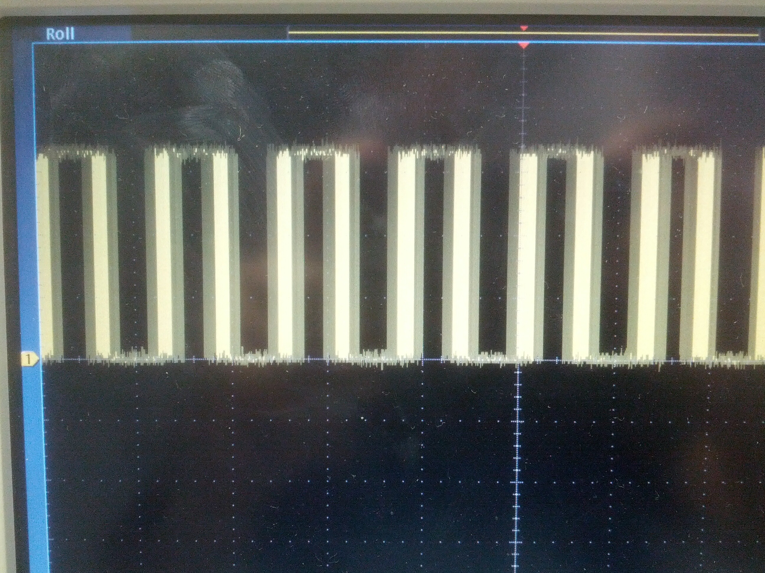
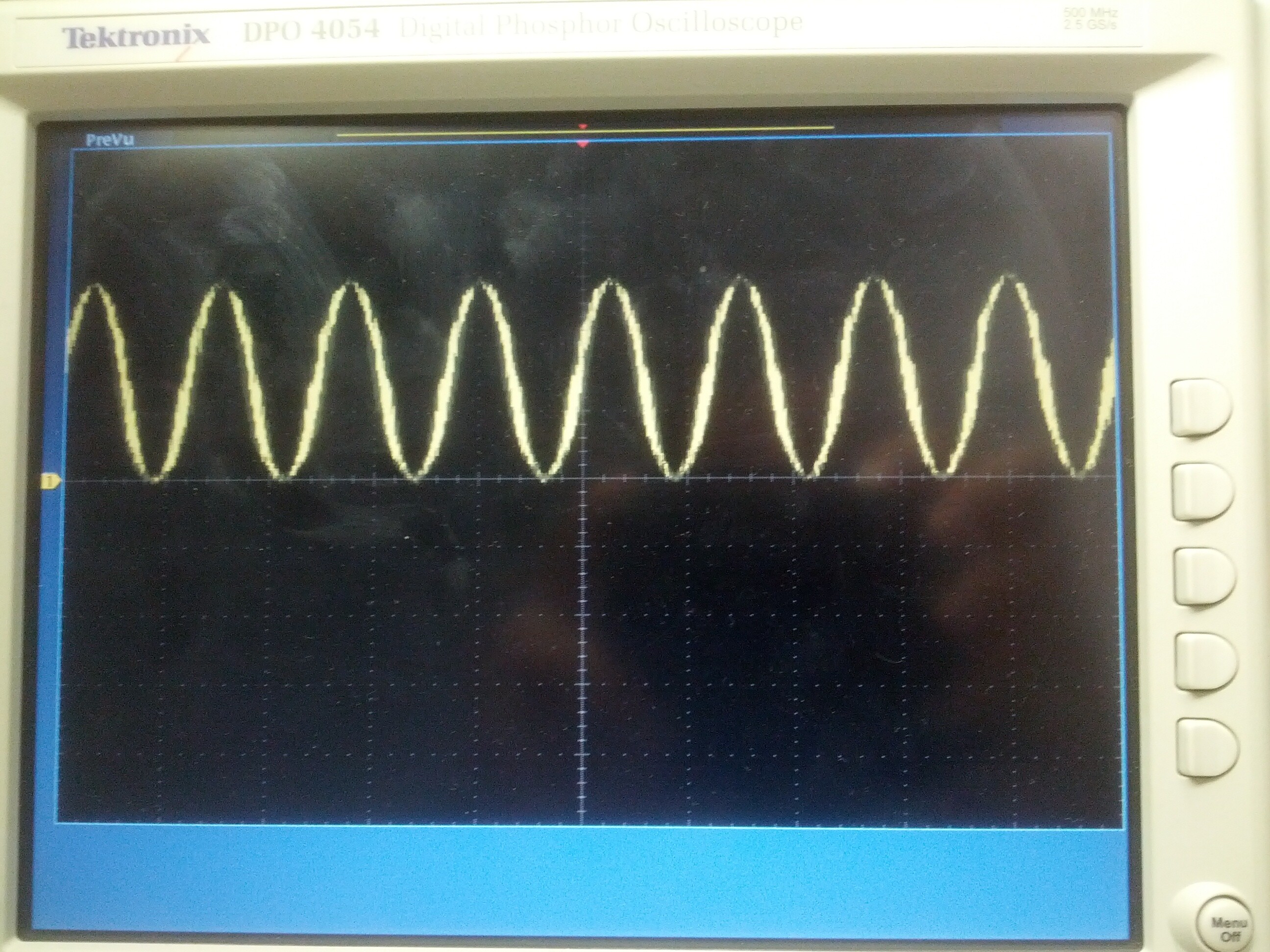
And those are the scrren shot images the first one is the pwm signal, the second one is the filterd pwm signal
my question is how to get a 120 degree phase shift between the pwm signals ?
how to get a 120 degree phase shift between the pwm signals
You need to access the second wave with an index that is one third further into the wave table than the first.
The best thing is if you have another variable for the second waves index that initially you start one third the way along then increment it each time in the loop and make sure it wraps round when it exceeds the table's length, sort of like this:-
// at the start of the loop function
static int k = tableLength /3;
// then later on when it comes to outputting the waveform
      analogWrite(2, sine[i]); // for your original wave
    k++;
  if(k > tableLength) k=0;
      analogWrite(9, sine[k]); // for the 120 degree shifted wave
@ Grumpy_Mike Thanks for you reply..
// at the start of the loop function
static int k = tableLength /3;
// then later on when it comes to outputting the waveform
analogWrite(2, sine*); // for your original wave*
- k++;*
- if(k > tableLength) k=0;*
- analogWrite(9, sine[k]); // for the 120 degree shifted wave*
[/quote]
Questions:
What do you actually mean with table length? Do you mean the number of the values of my sine look up table ?
The second question is can I actually apply your tipp to get not only 2 sognals in phase but three ?
My aim actually is to control an asynchrons motor
What do you actually mean with table length? Do you mean the number of the values of my sine look up table ?
Yes.
And yes, two thirds along.
You might want to have the number of samples in the table divisable by three.
@ Grimpy_Mike
Thanks for your reply.
So I modified my code to get 120 degree phase shift between each of the three signals
Here is my code firestly
// SINUS Signal über DAC an PWM Pin ausgeben


//1kHz

int sine[] = {2048,2305,2557,2802,3034,3251,3449,3625,3777,3901,3995,4059,4092,4092,4060,3996,3902,3778,3628,3452,3254,3037,2805,2560,2308,2051,1795,1542,1297,1065,847,649,473,321,197,102,37,4,4,35,99,193,316,466,642,839,1056,1288,1533,1785,2041};
static int k = 50/3; //length of the sine table =51
static int j= 33; //(2/3)*50 length of the sine table

// the setup routine runs once when you press reset:
void setup() {


  // initialize the digital pin as an output.
 // pinMode(led, OUTPUT);
  pinMode(2, OUTPUT);  //Phase 1
  pinMode(9, OUTPUT);  //Phase 2
  pinMode(12,OUTPUT);  //Phase 3
}

// the loop routine runs over and over again forever:
void loop() {


  for(int i = 0; i<50;i++){
      if(sine[i]>4095) {
         sine[i]=4095;
    //     digitalWrite(led, LOW);
     }
    analogWriteResolution(12);
    analogWrite(2, sine[i]); // original wave

   k++;
  if(k>51) k=0;

   analogWrite(9,sine[k]);//   for the 120 degree shifted wave


   j++;
   if(j>51) j=0 ;
   analogWrite(12,sine[j]);//   for the 240 degree shifted wave for the third wave

   //( delayMicroseconds(14);

   delay(10);
  }
}
Questions :
1:I didnt find an Arduino name to measure the length of an array like getlength() or so. So I wrote the array length per hand
2: I applied your
   k++;
  if(k>51) k=0;
But I dont know if it is true..
3: This is the output of my three signals. But I cant recognize any phase shift. Where is my failure ?
See pdf
Im really glad for your help
3 phase.pdf (89.7 KB)
You have to look at the signals on a two or four channel scope to see the phase shift.
Or use the externals trigger on one signal and look at the other two in turn.
Thanks
Do you think that my code modification cause of the phase shift is right ?
Im not sure
What do you think ?
You have a 2 channel scope. Use the 2nd channel to look at one of the 2 other waveforms, while still showing the 1st waveform.
Hi here are some screen shots
The first signal is the orignial one
The second signal is the one which should be 120 degree phase shifted
NewFile0.bmp (146 KB)
NewFile1.bmp (146 KB)
NewFile2.bmp (146 KB)
NewFile3.bmp (146 KB)