[SOLVED] Specific problem with a sensor with 0–5 V output and external PSU

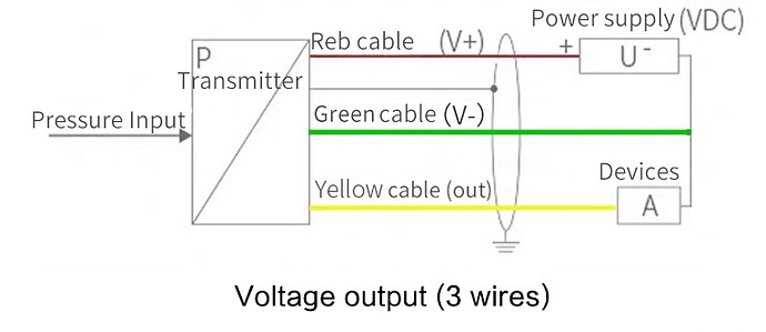
I have an Arduino-related problem with a 3-wire water pressure transducer that outputs 0–5 V through its yellow wire; the sensor takes 24 V DC from an external power supply that I have bought ad hoc (GACUN-2410, output 24 V 1.0 A). The sensor is QDY30A (https://www.aliexpress.com/item/1005004607235726.html), and its technical specs and schematics are below:

Now, I tried that the sensor works with a multimeter (the made-up figures in the figure below are in volts). I always thought that the sensor output loop's end has to be connected to ground, but to my surprise it actually needs to be connected to the 24 V power supply's negative wire or it just gives 0.00 V as the reading, regardless of the pressure.

I also tried to connect it to my Arduino Uno's A1 port, but all I got was the reading going from 1023 to 0 and then -> 1023 -> 0 -> 1023 -> 0 in a very rapid, endless cycle on my LCD shield's display.

The code should not pose a problem here, but I can share how I got those numbers. The code is heavily simplified (LCD shield's button-related things and SD data logger shield-related stuff removed) so there may be small errors.

//Sample using LiquidCrystal library
#include <LiquidCrystal.h>
 
// select the pins used on the LCD panel
LiquidCrystal lcd(8, 9, 4, 5, 6, 7);
int sensorOutput = 0;
char s[17];
 
void setup()
{
    sensorOutput=analogRead(A1);
    lcd.begin(16, 2);              // start the library
    Serial.begin(9600);
}


void loop()
{
    char s[17];
    lcd.setCursor(0,0);
    sensorOutput=analogRead(A1);

    lcd.setCursor(0,0);
    lcd.print("Sensor output");
    lcd.setCursor(0,1);
    sprintf(s,"%d",sensorOutput);
    lcd.print(s);
    delay(200);
 }

Now I'm puzzled about what to do: how to wire the sensor correctly to Arduino and make a working loop here so that I get a reading through an analog input port? As stated, the system works perfectly with a multimeter connected to the output wire and to the negative wire of the DC power supply, now I only need to transform this to work with Arduino.

The main objective here is to make a water level sensor for my well, with a constant reading on the LCD display (+ you can cycle through water volume and fill % with the LCD shield's buttons), and also log all values in the SD data logging module. I've researched this and found a similar project, but the post didn't address this specific question.

HI, @Scorpizoid
Welcome to the forum.

The sensor gnd and the controller gnd have to be connected together, this is so they all have the same gnd or 0V reference.

Your controller is the "Devices".

Tom.. :smiley: :+1: :coffee: :australia:

1 Like

My read on your sensor is it is powered by 24 VDC which is very common for sensors like you have. I also assume your sensor has a range of 0 to 2.0 meters corresponding to a 0 to 5.0 voltage out proportional to water depth. You have a low pressure sensor.

Next I assume an Arduino Uno or similar having a A/D (Analog to Digital) input of 0 to 5.0 volts. Since the sensor out is referenced to sensor ground your Arduino and your sensor need to share a common ground. You found that out.

So as things work out your Arduino uses a 10 bit analog to digital converter. What the AD will show is 0 to 1023 bits. That is what would be expected.

Next you want to convert the analog input to a unit of measure you want/need. 0 to 1023 bits to water level in a tank. This is where I suggest using a map function. A Google of Arduino Map Function should get you a how to use it. Arduino Map Function.

Something else to consider is for example that your AI (Analog In) has a reference which we assume to be 5.0 volts. This is not always the case. That needs considered but initially I would just keep it simple and fine tune later.

Ron

1 Like

Thanks @TomGeorge! So if I understand correctly, this setup should provide sensible readings:

@Ron_Blain thanks, indeed I need to do the calibration and conversion calculations and convert the AD signal bits to real-life data. Luckily it's all very easy once I get the electronics right. I was thinking about conducting a linearity test as well to see how the signal behaves as a function of depth. Hopefully it's linear, but it's no problem if it follows a quadratic equation. The sensor measures from 0 to 5 metres, i.e. 0 V is no water and 5 V is ≥5 m.

1 Like

Your last drawing is fine. Your Arduino and your sensor need to share a common ground as you drew it.

I would get some basic code working. Once you have that you can worry about converting your units like 0 to 1023 becomes 0 to 2.0 meters. You may want to convert to mm of water or cm of water level. Something else I am unsure of is how deep your well is before you hit the top of the water level. Once you have the basics working then you can calibrate things.

Ron

1 Like

Thanks, the system is now working perfectly, with the LCD showing the depth (in metres with two decimals if more than 1 metre and in cm if less than 1 metre), fill % and water amount in litres correctly.

Currently 3.9 metres; the overall depth is 5.0 m so there's 1.1 m of water.

Lesson of the day: finding a common ground makes things work not only in social situations, but also in electronics.

1 Like

Glad it all came together and worked out for you. :slight_smile:

Ron

1 Like

This topic was automatically closed 180 days after the last reply. New replies are no longer allowed.