I've been successfully using the NHD31OLED_2X_GR const for the screen.
how ever I don't need the extra grayscale resolution. and would have like to save the extra bits to improve FPS and go with
NHD31OLED_2X_BW. however, when doing this the screen will draw two bright lines at the edges that are on. is there a software solution to use the BW on a GR screen?
In 16 bit mode, the flag will extend the internal width of the display from 248 to 256. I assume the display actually has a width of 256 pixel, so the 16 bit mode is required.
I can not test the code, so i guess in the GR mode, it was set to blank, while in BW mode, it is set for some reason.
What means "successfully connected"? What is a noisy screen?
How are lines connected? Do they match the u8glib constructor?
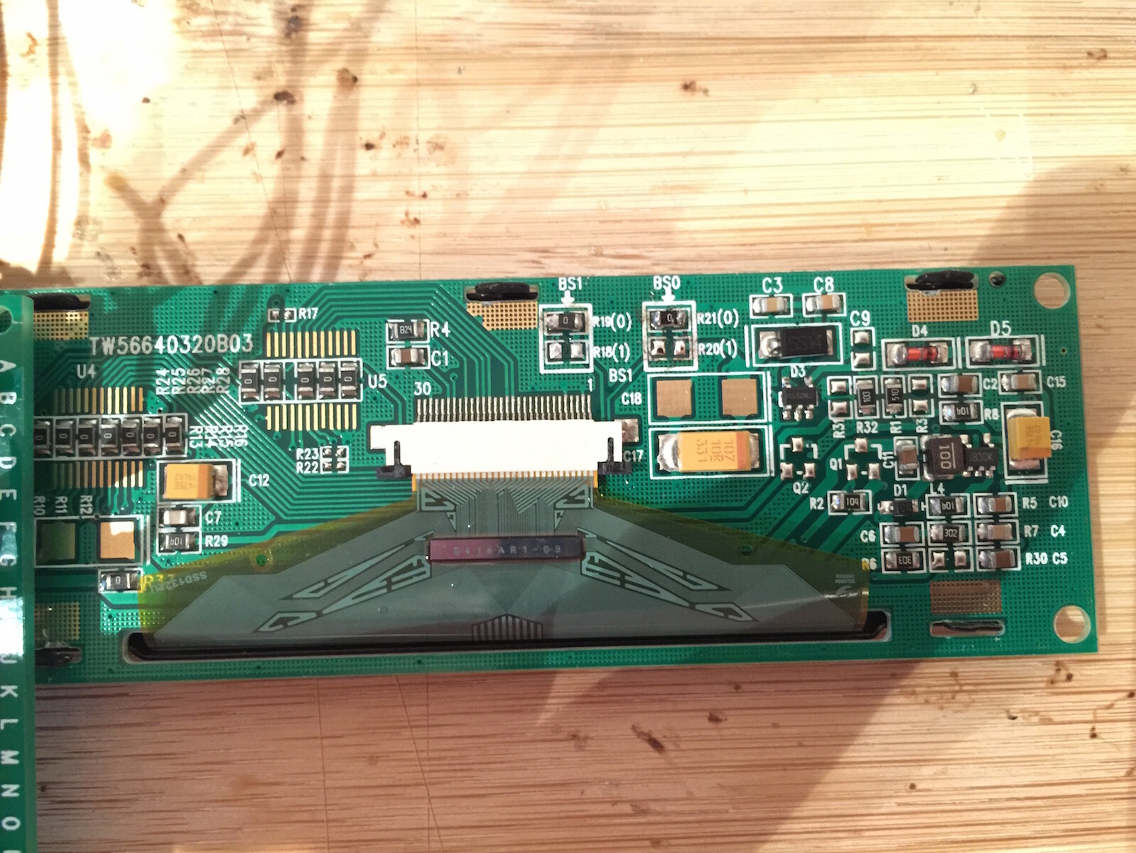
Maybe you can post a picture of the display and Arduino together.
Thanks to this thread, Oliver Kraus' inputs & u8glib graphics library I was able to enable an East Rising 256x64OLED model ER-OLEDM032-1G connected to Arduino Uno through the hardware SPI bus
Made a separate post before but Didn't realize there was already a similar thread going on.
I am trying to make a custom boost gauge using the 3.12" 256x64 SSD1322 display from New Haven using u8glib. The left half of the screen displays a static 128x64 bitmap, and the right half displays the PSI reading. Even while using Hardware SPI and a larger page height, the screen is not refreshing smooth enough for my liking.
The only three solutions I suppose are
First draw the the bitmap on the left side, then switch the column start address to the middle of the screen so now it only has half as many pixels to refresh. (not sure if this is possible?)
Same thing as above, but use two separate instances of u8g addressing each 128x64 halves of the display. (again, not sure if that's possible)
Run the display in parallel mode
Though to run in parallel mode would be the easiest solution, im having trouble figuring out how to run the display in parallel mode using u8glib. I tried setting the initial parameters as:
Hi
I have never tested this display in parallel mode. It should however work and often this is a hardware issue and not a software problem: Did you use level shifters? Are the RD and Reset lines wired correctly?
olikraus:
Hi
I have never tested this display in parallel mode. It should however work and often this is a hardware issue and not a software problem: Did you use level shifters? Are the RD and Reset lines wired correctly?
Oliver
No I am not using level shifters. My mistake, I keep forgetting this is not a 5v display .
I assumed the RW and Reset lines were not used? I tried running it with and without and still no luck.
The parameters using RW and Reset I wrote as
U8GLIB_NHD31OLED_BW u8g(2,3,4,5,6,7,8,9,10,11);
and still no luck. The names of the hardware pinouts don't seem to match up with the code. On the data sheet the pins for M68 Parallel are:
d0-d7, DC, RW, E, Reset and CS.
But the code only lists:
d0-d7, CS, DI, RW, Reset.
"di" (data/instruction) must be connected with the data/instruction/command line of the display (i guess this is DS). Unfortunately there is no common naming convention for this, so several names are there in the datasheets.
"rw" must be connected to "E" (6800 mode)
"reset" might be connected to the reset line of the display. If you do not connect the Arduino with the reset line, you still have to feed some usefull reset into the display (e.g. a signal from an RC network)
There is another line in the display, which must be connected correctly. If i remember correctly, this is the WR line from the 6800 mode. It must be connected to GND (not sure) so that the Arduino has write access. U8glib does not read from the display, so the hardware setup can be in such a way, that the software only has write access.