Hi,
I'm currently having a problem that I don't know how to solve easily, maybe someone can help me.
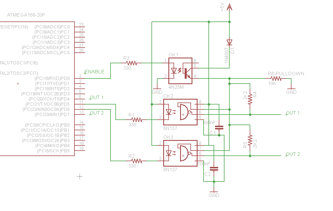
I'm working on a circuit that has 2 outputs that need to be isolated by optocouplers. I have used the 6N137 fast optocoupler that has open collector, so I put pull-up resistors on each one.
Since I needed the output in phase with the input, I connected 2 pins of the Atmega328p to the diode cathode of each optocoupler.
Now the problem is that when I reset the microcontroller all pins go to high impedance state (or at least I think so). I thought about this problem and put another optocoupler, a 4N25 to make an enable for both 6N137.
I tested this circuit but whenever I reset the microcontroller, during the bootloading time (1.5 sec) I get the output of my 4N25 high, giving the enable to the 6N137 optocouplers. I can't accept this, both "OUT 1" and "OUT 2" must be low during startup.
Could You attach the wiring diagram and code according to Forum standards? There is advice in the top of the page. That makes it easier for helpers.
Being the top designer for the controllers in heavy machines I understand Your problem. My steppers make a "hunk" when I reload or restart the controller.... It's okey for me.
An Arduino pin can source and sink.
Meaning you can connect an opto LED between pin and ground, or pin and VCC, for opposite behaviour.
But maybe it's your code (which you didn't post).
If you want to start a pin HIGH at bootup, it's common to enable the pull up resistors before setting the pin to output.
The pins start up in high impedance state. But if you have put pullup resistors on them, that will ensure that they go high while the pin is in high impedance state. Is that what you have? If so, remove them, they are unnecessary and causing you problems. Post schematic if not.
Thanks for the fast answers! @Wawa, the problem is the bootloader, since during the "bootloader time" (1.5 sec) the program does not control the microcontroller, all pins turn to high impedance state. @DrAzzy, both arduino pins 5 and 6 used for the 6N137 are settled as output, with low state in the setup section of the program, like this:
void setup() {
  pinMode(2, OUTPUT);    // Settles output pin enable
  digitalWrite(2, LOW);      // For security, disables logic voltage at 6N137
  analogWrite(5, 0);
  analogWrite(6, 0);
}
I put analogWrite instead of digitalWrite because I will apply PWM later on that pin. The problem is not caused by this section, the problem is caused by the hardware, I need help with the logic, another point of view if it is neccesary to change connections of implementing something like a monostable of 2 seconds triggered by the reset to enable a gate or something similar, because the microcontroller does not have the control over the circuit during startup
Maybe drive the opto leds with a pin and an inverter each so when the pin is LOW the opto led is ON.
AVR IO pins start as INPUT LOW by default, inverters would turn that HIGH or am I wrong?
Thank you GoForSmoke! The solution was inverting the output pin from the microcontroller, and removing the "enable optocoupler" 4N25.
I used a transistor not gate for both 6N137, like this https://www.electronics-tutorials.ws/logic/log47.gif.
Then I connected the fast opto's led in parallel with the transistor, so that when pin is HIGH the opto is dark.
During bootloading time this circuit gives a low output, that is what I was looking for.