I have been looking for about 2 days for a good way to generate sound from an Arduino PWM wave (e.g. Tone library), using LTSpice to simulate everything, but I keep seeing high distortion or low efficiency. Since I'm quite unexperienced in this field I decided to post my question here, to make sure I get the basics right.
So ,I can't send the PWM wave straight into a speaker, because then I would get a 2.5V DC bias into that speaker (not good as far as I read), high distortion because of the square wave, and most importantly , not enough power. Arduino Mega delivers 10 mA if you want to stay away from the max. limits, and I need 600mA for the speaker (4 Watts, 8ohm). So I need to double the voltage (5V p-p instead of 2.5V) and get a much higher current. I have 5V, 9V and 24V available.
I've found some amplifier circuits online, but they all have problems:
http://www.electronics-tutorials.ws/amplifier/amp31.gif?81223b
Speaker between Vou and 0V would work, if the resistors in series with the transistor are very low (I need 5V over the speaker). Result: high power loss (easily 70%). Since I'm working on batteries I want to avoid this dissipation of 5-6 watts.
http://www.electronics-tutorials.ws/amplifier/amp47.gif?81223b
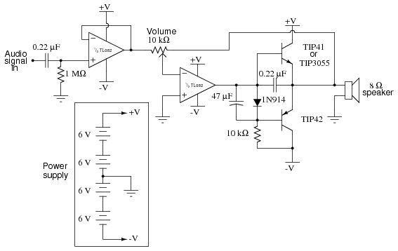
Could work, but has some disadvantages which were solved by this one: http://www.ibiblio.org/kuphaldt/electricCircuits/Exper/05320.png
They both work fine with AC signals 0.5Vp-p I suppose, but again. Mine is 2.5V p-p. So I need to lower it through voltage division, and at the same time low-pass filter it (remove distortion square wave) and high pass filter it (to remove DC bias). This contradicts. And if I want 15kHz to pass I can't get a sine wave out of 2kHz with the same low pass filter. Additionally I don't have -9V so I need to use virtual ground, which gets complicated.
So I thought: if I have to go to 0.5V p-p anyway, why shouldn't I use an amplifier chip, like a TI LM384. This simplifies my work. But even then I still wonder how I can get from 0 - 5V pulse to -0.5 - +0.5V sine wave in the complete 2kHz - 15kHz spectrum. And do I have to do this before or after the amplification? I think in case of a chip I need to do it before. But is that the best choice?
Perhaps I'm going too far? Is a DC current really a problem? Do I really need a +- sine wave or will my speaker also sound OK with a square wave?
Here I got a bit lost... Can anyone point me in the right direction?
If you want direct sound from an Arduino pin, use a 120ohm resistor (absolute minimum!), a 100uF capacitor, and a speaker, all in series, from pin to ground.
of the electrolytic cap on the Arduino side.
Volume will be VERY low.
Or try a small amplifier module.
Use a 10k resistor and 100n cap in series between Arduino and amp input.
Best to get one with a volume pot.
Firstly there are clever techniques to improve the effective resolution of the PWM
from say 8 bits or less to 16 or more by "noise shaping". This allows a high PWM frequency
to be used that can be filter out from the audio. The 16MHz frequency of the Arduino
allows 8 bit PWM to run at 62.5kHz, which is ultrasonic and thus easy to filter out
(the speaker and your ears will do the job!)
The way to amplify a PWM output is class-D - the output is boosted by a half-H-bridge
to high current version (or higher voltage, higher current). You can take the complement
of the signal and boost that too, allowing a full-bridge class D output stage, meaning no
large electrolytic blocking capacitor is needed.
Noise shaping:
With two integrating stages this looks like:
int acc = 0 ;  // integration state
int acc2 = 0 ;

void noise_shape (int sample)  // here sample is signed 16 bit value
{
  acc += sample ;  // two integral stages
  acc2 += acc ;
  int top_part = acc2 & 0xFF00 ;   // get 8 bits to be output
  acc -= top_part ;  // feedback negatively to both integral stages
  acc2 -= top_part ;
  analogWrite (pwm_pin, 0xFF & (top_part >> 8)) ;
}
Perhaps I'm going too far? Is a DC current really a problem?
Yes, but as Wawa says, a capacitor will block it. Most amplifier circuits have an input capacitor (and there's probably one on the input of your computer speakers) but it's a good idea to have another one on the Arduino output too unless everything is hard wired.
Do I really need a +- sine wave or will my speaker also sound OK with a square wave?
It depends on what kind of sound you want! If you want to hear the difference between a sine wave and a square wave, [u]Audacity[/u] (FREE) has a Generate Tone function and with a couple of clicks you an generate sine & square waves and listen to them on your computer.
You can get a pure square wave (or rectangle wave) from the Arduino, but you're not going to get a pure sine wave from the Arduino's PWM.