As I understand, this is implemented to fight a white noise, but it's not the best way do it.
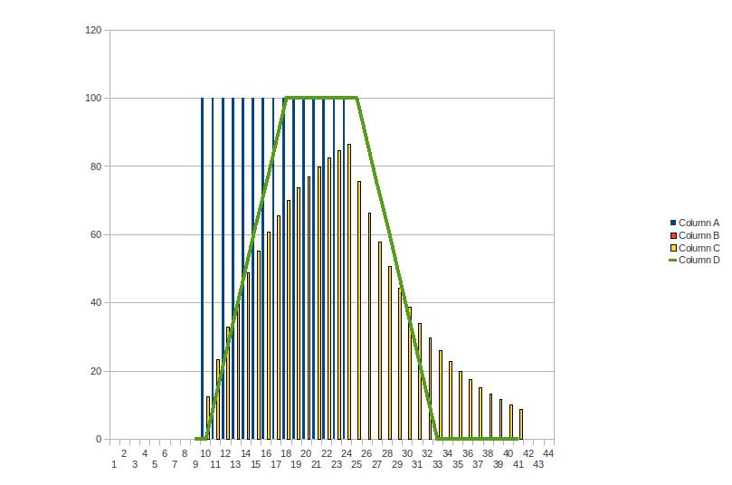
Inserting averaging or "software" Low Pass Filter would greatly smoothed edges of the incoming signal.
Better option is to implement "moving average filter".
Attached doc shows a difference.
do you think you could post your complete sketch, with the interrupts and the dsp and all that?
Sure, on the condition that you won't just copy/paste it without checking. Also as this is a snapshot middle in the process of coding and learning there can/will be things that are not so correct or even plain wrong. Serial.prints in isr for example.
#define LEDPIN 13
#define USEPRESCALER 3
#define DEADBAND 26

#define NUMBEROFSENSORS 4
volatile unsigned int counterStamps[NUMBEROFSENSORS] = {
  0, 0, 0, 0};   // 4 timestamps are used.
volatile unsigned int smoothedValues[NUMBEROFSENSORS] = {
  0, 0, 0, 0};
volatile byte sensorNumber = 0;
volatile byte newValue = 0;
volatile byte deadband = DEADBAND;
volatile unsigned int counter = 0;
volatile byte running = 0;

void setup()
{
  bitClear(TIMSK0, TOIE0);  // no more timer0 overflow interrupt! No more: micros(), millis(), delay()

  pinMode(LEDPIN, OUTPUT);
  Serial.begin(115200);
  Serial.println("Started.");
  Serial.println();


  analogInit8Bit(USEPRESCALER);
  delayMillis(1000);
  attachAnalogInterrupt();

}

void loop()
{
  if (Serial.available() > 0)
  {
    byte incoming = Serial.read();
    if (incoming == '=')
    {
      deadband++;
      Serial.println(deadband, DEC);
    }
    else if (incoming == '-')
    {
      deadband--;
      Serial.println(deadband, DEC);
    }
    else if (incoming == '0')
    {

      Serial.println("Reset");
      attachAnalogInterrupt();
    }
  }
}

SIGNAL(ADC_vect)
{
  PORTB = B00100000;      // led pin 13 on
  newValue = ADCH;

  smoothedValues[sensorNumber] = (smoothedValues[sensorNumber] - (smoothedValues[sensorNumber] / 8)) + (newValue / 8);
  //smoothedValues[sensorNumber] = (smoothedValues[sensorNumber] + newValue) / 2;

  if (newValue > (smoothedValues[sensorNumber] + deadband) && counterStamps[sensorNumber] == 0)
  {
    counterStamps[sensorNumber] = counter;

//    Serial.print(newValue, DEC);
//    Serial.print(",");
//    Serial.print(smoothedValues[sensorNumber], DEC);
//    Serial.print(",");
//    Serial.println(sensorNumber, DEC);

    if (counterStamps[0] && counterStamps[1] && counterStamps[2] && counterStamps[3]) // all triggered
    {
       detachAnalogInterrupt();
       for (byte sensor = 0; sensor < NUMBEROFSENSORS; sensor++)
       {
         Serial.print(counterStamps[sensor], DEC);
         Serial.print(",");
       }
       Serial.println();
       Serial.println("Done");
    }
 }

  counter++;

  sensorNumber++;
  if (sensorNumber == NUMBEROFSENSORS )
  {
    sensorNumber = 0;                  // roll over.
  }

  // Here i change to another analog input. Note that there is already a conversion taking place. Change of input will take affect _after_ the current conversion is complete. Be sure to check which return value belongs to which sensor.
  // AVCC with external capacitor at AREF pin(arduino default)
  // left adjusted. ADLAR = 1
  // input pin
  ADMUX = (DEFAULT << 6) | (1 << ADLAR) | (sensorNumber & 0x07);

  PORTB = B00000000;      // led pin 13 off
}

void attachAnalogInterrupt()
{
  clearArrays();

  counter = 0;
  sensorNumber = 0;
  running = 1;

  ADMUX = (DEFAULT << 6) | (1 << ADLAR) | (sensorNumber & 0x07);
  ADCSRB = B00000000;  // Auto Trigger Source = Free Running mode. ADTS = 000

    // start conversion.     bitSet(ADCSRA, ADSC)
  // Auto Trigger Enable.  bitSet(ADCSRA, ADATE)
  // interrupt enable.     bitSet(ADCSRA, ADIE)
  ADCSRA |= (1 << ADSC) | (1 << ADIE) | (1 << ADATE);


}

void detachAnalogInterrupt()
{
  running = 0;
  bitClear(ADCSRA, ADIE);  // interrupt disable.
}

void analogInit8Bit(byte preS)
{
  DIDR0 = B00111111;  // disable all digital input buffers

  // AVCC with external capacitor at AREF pin(arduino default)
  // left adjusted. ADLAR = 1
  ADMUX = (DEFAULT << 6) | (1 << ADLAR);

  // enable a2d conversions
  // set prescaler
  ADCSRA = preS | (1 << ADEN);
}

void delayMillis(int mil)
{
  do
  {
    delayMicroseconds(1000);
    mil--;
  }
  while ( mil );
}

void clearArrays()
{
  for (byte sensor = 0; sensor < NUMBEROFSENSORS; sensor++)
  {
    counterStamps[sensor] = 0UL;
    smoothedValues[sensor] = 0UL;
  }
}

byte analogRead8Bit(byte pin)
{
  // set the analog reference (high two bits)
  // set ADLAR. Left adjusted. (5th bit)
  // select the channel (low 4 bits).
  ADMUX = (DEFAULT << 6) | (1 << ADLAR) | (pin & 0x07);

  // start the conversion
  bitSet(ADCSRA, ADSC);

  // ADSC is cleared when the conversion finishes
  while (bit_is_set(ADCSRA, ADSC));

  return ADCH;
}
Please, the above is not intended as final, finished nor correct. Copy with care. Reason i did post this was because it was explicitly asked by jigajigajoo.
Yot:
Sure, on the condition that you won't just copy/paste it without checking. Also as this is a snapshot middle in the process of coding and learning there can/will be things that are not so correct or even plain wrong. Serial.prints in isr for example.
A couple quick question about your code (I feel like even if I can't put together the code right at least I should learn why you decided to things a certain way):
if (counterStamps[0] && counterStamps[1] && counterStamps[2] && counterStamps[3]) // all triggered
{
detachAnalogInterrupt();
Why did you include your detachInterrupt in your isr instead of in the standard loop? Now that I think about it thats a better place to put it, but was there an actual reason why (ie something about interrupts which I dont know about) or was it mainly arbitrary (for example i put my checksensors-and-detach in the main loop).
EDIT: Oh duh, just realized that the interrupt keeps running, waiting for the loop() to turn it off. So I see why you would put it there. New question, then: Obviously theres a limit to how many instructions you can run during the isr, but how would you know when you hit that? (would the arduino crash/reset, or would you get junk data?...)
volatile byte running = 0;
Does using volatile variables (ie saving vars in eeprom vs ram) slow down the code at all? I was just curious, I think I do the same thing for the most part.
Anyways, your code is almost the same as the stuff I put together. I'm curious as to whether your code works that well, because for some reason on mine, I get all sorts of crazy values for the counter. I have a feeling its because not all of my variables are volatile, which I'll fix, but in general because I missed some key point. I'll keep working on it, but thanks for the code example! ?
Why did you include your detachInterrupt in your isr instead of in the standard loop?
No other reason than that was the place where i was busy at that time and wanted to stop the interrupt from happening again. With other words, result of playing with code. Not meant to be that way in the end as i don't find this particular easy to follow/understand. Neither the serial.prints inside the isr, even if it doesn't mess with the interrupt.
No, it's not my intention to keep the sampling running after the 4 sensors are triggered. Only thing i do in loop() is checking for serial commands.
If you check the led on pin 13 (with a scope/logic analyzer) you will see pulses at same freq. of the samplerate. When the led goes off for some period of time you are ok, if the led stays on or has a weird freq. you know the isr takes up too much time.
It doesn't matter if using the volatile is slower/faster, it's a necessity if the variable is read/written inside the isr as well as outside the isr. Because i'm just coding along i made the most variables volatile.
Not sure why your code doesn't work but the code i showed you is version, -checks project folder-, version 14. I started with 1 sensor and one of the analog/serial examples and saved a sketch at every major accomplishment. I spend hours staring at plotted samples and so on. Even the datasheet is growing on me. Also my sketch assumes that the analog values are a representation of volume, not like the real sound wave.
Also I noticed some bleed between analog read values when the prescaler is set < 5 (two sensor values are exact same when def shouldnt be). I'm wondering whether you're getting that problem too.
Very sure i am. Just haven't checked/measured for it yet. Work in progress.
May i have a guess for which sensors the values are the same where they shouldn't?
Your very first 2 samples.
If i'm right:
That's one of the tricky parts of using the adc self triggering together with changing input pins inside the isr. You may want to draw out (dead tree ftw.) the exact sequence of events. Where in time does a conversion start/finish, where is the isr called, when is the new input pin processed so the next value is from that pin.
Hey guys,
I wanted to give an update on this thread, if anyone else ever pops up onto the thread.
I dumped the amplitude analysis idea, because it was just way too noisy/inaccurate for the sampling rate. I started putting a lot of research time into time delay estimation, and beamforming. These are two different techniques to localize sound accurately (the first is less accurate but more computationally efficient), but they both require way more processing power than the arduino supplies.
Therefore I loaded up Octave (matlab clone) on my computer and started playing around with algorithms utilizing the above. I'm still having a huge amount of trouble understanding the theory, wading through research paper after research paper, and trying to implement them, but that's not a problem for this thread :D.
I'm getting a Maple (Maple | LeafLabs), which is like a souped-up $50 version of the Arduino, complete with 72 MHz processor speed, and 1 MHz ADC max sampling rate. It even clones the Arduino IDE, with the same language and everything. I'll let you guys know whether that ever works.
Octave is a good tool. Audacity is pretty good for viewing the audio signals too.
You might think about recording several scenarios in which you know the locations of the speakers/mics.
Load those up and try your analysis. I highly recommend figuring out a way to visual the signal and your computations.
If you figure out what the important attributes and computations are, I think it's likely you could do it on an arduino (depending on the rest of the complexity of the project). But, it's harder to do all the initial testing on the arduino.
 Also my sketch assumes that the analog values are a representation of volume, not like the real sound wave.