Spectrum Analyzer - Adjustable Threshold via Potentiometer

Hi tom321...
I attempted the correction you pointed out but it didn't make a difference.

I did notice that if I commented out these two lines, the serial monitor posts kinda as it should.

void frequencyGraph(uint8_t x[], int size) {

//int data = analogRead(A2);
//int potSet = map(data, 0, 1023, 0, 255);
int top_threshold = potSet;

and if I comment out just one line, the serial monitor posts the out puts on a single line with no line breaks.

void frequencyGraph(uint8_t x[], int size) {

int data = analogRead(A2);
//int potSet = map(data, 0, 1023, 0, 255);
int top_threshold = potSet;

Also, noticed that my initial declaration of potSet can't be zero... it needs to be a value greater than zero to post on the serial monitor.

//int potSet = 0;
int potSet = 35;

I am willing to help you learn to fix your program, but I will not make changes for you. You have discovered how much harder it is to modify someones program than it is to write one from scratch.
But you do not want to learn, so good luck.

what the difference you have on serial monitor when you change 5 to 50 or 100 ?

Good point. I was wondering if it wouldn’t make more sense to map the analog in to a range of, for example, 1-10?

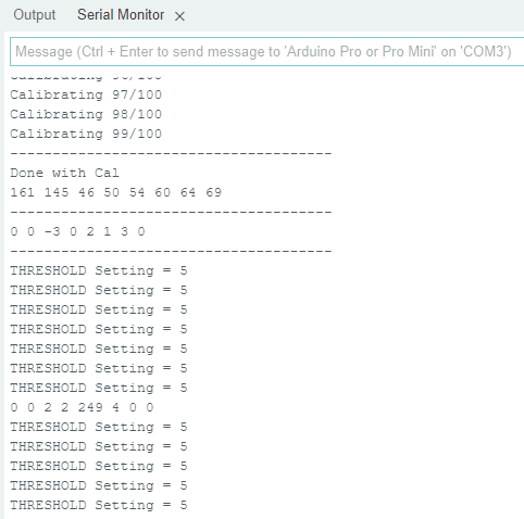
In the original code, I can set the threshold to any value between 1 and 255 and I get this output :

and if I change it to 100, I get...

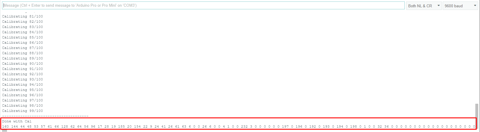
In the original code, If I set the threshold to zero (0) and I get this output - everything circled in red should be new lines below and I don't get any posts regarding the threshold value like above:

That seems funny to me that it behaves this way - doesn't it?

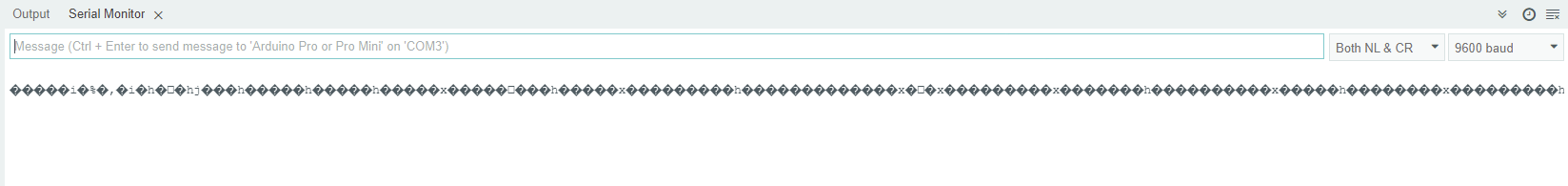
So, when I attempt to replace Threshold value with the pot setting, the code gets all jacked.
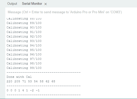
In this latest attempt. The serial Monitor pauses after the calibration routine and doesn't post and pin A0 outputs nor any A2 outputs (for the threshold/potSet).

/* 
* Christmas Light Controller & Real Time Frequency Analyzer based on FHT code by Open Music Labs at http://openmusiclabs.com
* 
* Then modified by PK from : https://dqydj.com/build-your-own-real-time-frequency-analyzer-and-christmas-light-controller/
*
* Modified by dimecoin: https://github.com/dimecoin/XmasFHT
*
* Requires FHT library, from here: 
* 	http://wiki.openmusiclabs.com/wiki/ArduinoFHT
*/

/////////////////////////////////////////////////////////////////////
// Easy Customizations
/////////////////////////////////////////////////////////////////////

// Adjust the Treshold - what volume should make it light up?
#define THRESHOLD A2
int potSet = 35;


// Old way if you want to statically set this.
// Attempt to 'zero out' noise when line in is 'quiet'.  You can change this to make some segments more sensitive.
// defaults: 
// { 100, 81, 54, 47, 56, 58, 60, 67 };
//int oct_bias[] = { 0, 0, 0, 0, 0, 0, 0, 0 };

// New Auto calibration.
uint8_t oct_bias[] = { 0, 0, 0, 0, 0, 0, 0, 0 };
uint16_t cal_bias[] = { 0, 0, 0, 0, 0, 0, 0, 0 };

/* Number of times to sample the "natural noise" on wires to get average.
 * This average is used to cancel out noise while running.
 * Don't call to many times or will be slow to startup.  
 * Dont' call over 16777215 or so times or it might overflow (plus would take forever to startup).
	ie. 256 (max reading) * CAL_TIME needs to be <= (2^32)-1 (size in bits of unint16_t)
*/

#define CAL_TIME 100

// Divide Threshold by 2 for top octave? 1 - yes 2 - no.  Makes highest frequency blink more.
#define TOP_OCTAVE_DIVIDE false //was false - SPJ

// This is for ACTIVE HIGH relays (works with LEDS for testing), switch values if you have ACTIVE LOW relays.
#define ACTIVE_ON HIGH //was HIGH - SPJ
#define ACTIVE_OFF LOW //was LOW - SPJ

// enable for serial mode output, comment out to speed up lights
#define DEBUG  //was Uncommented - SPJ

// Timer/delay for self test on startup.
#define SELFTESTTIME 100

/////////////////////////////////////////////////////////////////////
// Hard Customizations - know what you are doing, please.
/////////////////////////////////////////////////////////////////////
// FHT defaults - don't change without reading the Open Music Labs documentation at openmusiclabs.com
#define LOG_OUT 1		// use the log output function
#define FHT_N 256		// set to 256 point fht
#define OCTAVE 1
#define OCT_NORM 0

// include the library, must be done after some of the aboves are defined.. (required by FHT, won't work if included in wrong order)
#include <FHT.h>

// Delay - defines how many cycles before the lights will update.  OML's algorithm at 256 samples (needed for our 8 octaves) takes
// 3.18 ms per cycle, so we essentially throw out 14 cycles (I used mechanical relays, you can lower this for solid state relays).
// 15 cycles = 47.7 ms update rate.  Be careful here and don't change it too quickly!  I warned you!
// Default is 15
#define DELAY 5 //was 15 - SPJ

// Don't change NUM_PINS.  FHT outputs 8 octs.
#define NUM_PINS 8
// Pin configuration, there is only 8 channels here.  Add duplicate entries if you don't have 8 lights, must be 8!
int relayPins[] = { 2, 3, 4, 5, 6, 7, 8, 9 };

uint8_t x[NUM_PINS];


void frequencyGraph(uint8_t x[], int size);

void setup() {

	// pin setup
	for (int i = 0; i < NUM_PINS; i++) {
		pinMode(relayPins[i], OUTPUT);
		digitalWrite(relayPins[i], ACTIVE_OFF);
	}

	// quick self test
	for (int i = 0; i < 2; i++) {
		for (int j = 0; j < NUM_PINS; j++) {
			digitalWrite(relayPins[j], ACTIVE_ON);
			delay(SELFTESTTIME);
			digitalWrite(relayPins[j], ACTIVE_OFF);
		}
	}

#ifdef DEBUG
	Serial.begin(9600);
	while (!Serial) {
	};
#endif

	TIMSK0 = 0;		// turn off timer0 for lower jitter
	ADCSRA = 0xe5;		// set the adc to free running mode

	// This is setting up A0 - dime
	ADMUX = 0x40;		// use adc0
	DIDR0 = 0x01;		// turn off the digital input for adc0

}

/**********************************************************************************
  Loop - includes initialization function and the full loop
  
**********************************************************************************/

void loop() {

  //int data = analogRead(A2);
  //int potSet = map(data, 0, 1023, 0, 255);


	// True full loop
	int q = 0;
	int cal = 0;

	while (1) {		// reduces jitter

		cli();		// UDRE interrupt slows this way down on arduino1.0

		for (int i = 0; i < FHT_N; i++) {	// save 256 samples
			while (!(ADCSRA & 0x10)) ;	// wait for adc to be ready
			ADCSRA = 0xf5;	// restart adc

			// This is his way of reading Analog 0 (A0).  It pulls in L[ow] and H[igh] bit. - dimecoin
			byte m = ADCL;	// fetch adc data
			byte j = ADCH;

			int k = (j << 8) | m;	// form into an int
			k -= 0x0200;	// form into a signed int
			k <<= 6;	// form into a 16b signed int
			fht_input[i] = k;	// put real data into bins
		}

		fht_window();	// window the data for better frequency response
		fht_reorder();	// reorder the data before doing the fht
		fht_run();	// process the data in the fht
		fht_mag_octave();	// take the output of the fht

		sei();

		// We are in calibration mode.
		if (cal < CAL_TIME) {

			for (int i = 0; i < NUM_PINS; ++i) {
				cal_bias[i] += fht_oct_out[i];
			}

#ifdef DEBUG
			Serial.print(F("Calibrating "));
			Serial.print(cal);
			Serial.print(F("/"));
			Serial.println(CAL_TIME);
#endif

			cal++;
			continue;
		}
		// Calibration mode has just ended, crunch data collected.
		if (cal == CAL_TIME) {

			for (int i = 0; i < NUM_PINS; ++i) {
				oct_bias[i] = (uint8_t) (cal_bias[i] / CAL_TIME);
			}

#ifdef DEBUG
			Serial.println(F("--------------------------------------"));
			Serial.println(F("Done with Cal"));

			for (int i = 0; i < NUM_PINS; ++i) {
				Serial.print(oct_bias[i]);
				Serial.print(" ");
			}

			Serial.println(F(""));
			Serial.println(F("--------------------------------------"));

			for (int i = 0; i < NUM_PINS; ++i) {
				Serial.print(fht_oct_out[i] - oct_bias[i]);
				Serial.print(F(" "));
			}
			Serial.println(F(""));
			Serial.println(F("--------------------------------------"));

			Serial.flush();

#endif

			// Ready signal.
			for (int i = 0; i < NUM_PINS; i++) {
				digitalWrite(relayPins[i], ACTIVE_ON);
			}
			for (int i = 0; i < NUM_PINS; i++) {
				digitalWrite(relayPins[i], ACTIVE_OFF);
			}

			cal++;
			continue;
		}
		// Normal play mode

		if (q % DELAY == 0) {

			for (int i = 0; i < NUM_PINS; i++) {
				x[i] = fht_oct_out[i] - oct_bias[i];
			}

			frequencyGraph(x, NUM_PINS);


#ifdef DEBUG
			for (int i = 0; i < NUM_PINS; ++i) {
				Serial.print(x[i]);
				Serial.print(F(" "));
			}
			Serial.println(F(""));
#endif

		}

		++q;
	}

}

void frequencyGraph(uint8_t x[], int size) {

int data = analogRead(A2);
int potSet = map(data, 0, 1023, 0, 255);
int top_threshold = potSet;

	for (int i = 0; i < size - 1; i++) {
		x[i] = max(x[i], 0);

		// Special logic for last pin
		if (TOP_OCTAVE_DIVIDE && i == (size - 1)) {
			top_threshold /= 2;
		}

		if (x[i] >= top_threshold) {
			digitalWrite(relayPins[i], ACTIVE_ON);
		} else if (x[i] < top_threshold) {
			// && digitalRead(relayPins[i]) == ACTIVE_ON ) {
			digitalWrite(relayPins[i], ACTIVE_OFF);
		}
      Serial.print("Potentiometer Setting = ");
      Serial.println(potSet);
	}

}

that is wrong, you declare pin number as threshold value, must be value of the potentiometer = analogRead( A2);

OK... funny, cause I got that from this tutorial:
https://roboticsbackend.com/arduino-potentiometer-complete-tutorial/

Regardless, I tried changing it as follows, but I still get a stalled out program and serial monitor.

This is the latest code I tried.

/* 
* Christmas Light Controller & Real Time Frequency Analyzer based on FHT code by Open Music Labs at http://openmusiclabs.com
* 
* Then modified by PK from : https://dqydj.com/build-your-own-real-time-frequency-analyzer-and-christmas-light-controller/
*
* Modified by dimecoin: https://github.com/dimecoin/XmasFHT
*
* Requires FHT library, from here: 
* 	http://wiki.openmusiclabs.com/wiki/ArduinoFHT
*/

/////////////////////////////////////////////////////////////////////
// Easy Customizations
/////////////////////////////////////////////////////////////////////

// Adjust the Treshold - what volume should make it light up?
int THRESHOLD =analogRead(A2);


// Old way if you want to statically set this.
// Attempt to 'zero out' noise when line in is 'quiet'.  You can change this to make some segments more sensitive.
// defaults: 
// { 100, 81, 54, 47, 56, 58, 60, 67 };
//int oct_bias[] = { 0, 0, 0, 0, 0, 0, 0, 0 };

// New Auto calibration.
uint8_t oct_bias[] = { 0, 0, 0, 0, 0, 0, 0, 0 };
uint16_t cal_bias[] = { 0, 0, 0, 0, 0, 0, 0, 0 };

/* Number of times to sample the "natural noise" on wires to get average.
 * This average is used to cancel out noise while running.
 * Don't call to many times or will be slow to startup.  
 * Dont' call over 16777215 or so times or it might overflow (plus would take forever to startup).
	ie. 256 (max reading) * CAL_TIME needs to be <= (2^32)-1 (size in bits of unint16_t)
*/

#define CAL_TIME 100

// Divide Threshold by 2 for top octave? 1 - yes 2 - no.  Makes highest frequency blink more.
#define TOP_OCTAVE_DIVIDE false //was false - SPJ

// This is for ACTIVE HIGH relays (works with LEDS for testing), switch values if you have ACTIVE LOW relays.
#define ACTIVE_ON HIGH //was HIGH - SPJ
#define ACTIVE_OFF LOW //was LOW - SPJ

// enable for serial mode output, comment out to speed up lights
#define DEBUG  //was Uncommented - SPJ

// Timer/delay for self test on startup.
#define SELFTESTTIME 100

/////////////////////////////////////////////////////////////////////
// Hard Customizations - know what you are doing, please.
/////////////////////////////////////////////////////////////////////
// FHT defaults - don't change without reading the Open Music Labs documentation at openmusiclabs.com
#define LOG_OUT 1		// use the log output function
#define FHT_N 256		// set to 256 point fht
#define OCTAVE 1
#define OCT_NORM 0

// include the library, must be done after some of the aboves are defined.. (required by FHT, won't work if included in wrong order)
#include <FHT.h>

// Delay - defines how many cycles before the lights will update.  OML's algorithm at 256 samples (needed for our 8 octaves) takes
// 3.18 ms per cycle, so we essentially throw out 14 cycles (I used mechanical relays, you can lower this for solid state relays).
// 15 cycles = 47.7 ms update rate.  Be careful here and don't change it too quickly!  I warned you!
// Default is 15
#define DELAY 5 //was 15 - SPJ

// Don't change NUM_PINS.  FHT outputs 8 octs.
#define NUM_PINS 8
// Pin configuration, there is only 8 channels here.  Add duplicate entries if you don't have 8 lights, must be 8!
int relayPins[] = { 2, 3, 4, 5, 6, 7, 8, 9 };

uint8_t x[NUM_PINS];


//void frequencyGraph(uint8_t x[], int size);

void setup() {

	// pin setup
	for (int i = 0; i < NUM_PINS; i++) {
		pinMode(relayPins[i], OUTPUT);
		digitalWrite(relayPins[i], ACTIVE_OFF);
	}

	// quick self test
	for (int i = 0; i < 2; i++) {
		for (int j = 0; j < NUM_PINS; j++) {
			digitalWrite(relayPins[j], ACTIVE_ON);
			delay(SELFTESTTIME);
			digitalWrite(relayPins[j], ACTIVE_OFF);
		}
	}

#ifdef DEBUG
	Serial.begin(9600);
	while (!Serial) {
	};
#endif

	TIMSK0 = 0;		// turn off timer0 for lower jitter
	ADCSRA = 0xe5;		// set the adc to free running mode

	// This is setting up A0 - dime
	ADMUX = 0x40;		// use adc0
	DIDR0 = 0x01;		// turn off the digital input for adc0

}

/**********************************************************************************
  Loop - includes initialization function and the full loop
  
**********************************************************************************/

void loop() {

	// True full loop
	int q = 0;
	int cal = 0;

	while (1) {		// reduces jitter

		cli();		// UDRE interrupt slows this way down on arduino1.0

		for (int i = 0; i < FHT_N; i++) {	// save 256 samples
			while (!(ADCSRA & 0x10)) ;	// wait for adc to be ready
			ADCSRA = 0xf5;	// restart adc

			// This is his way of reading Analog 0 (A0).  It pulls in L[ow] and H[igh] bit. - dimecoin
			byte m = ADCL;	// fetch adc data
			byte j = ADCH;

			int k = (j << 8) | m;	// form into an int
			k -= 0x0200;	// form into a signed int
			k <<= 6;	// form into a 16b signed int
			fht_input[i] = k;	// put real data into bins
		}

		fht_window();	// window the data for better frequency response
		fht_reorder();	// reorder the data before doing the fht
		fht_run();	// process the data in the fht
		fht_mag_octave();	// take the output of the fht

		sei();

		// We are in calibration mode.
		if (cal < CAL_TIME) {

			for (int i = 0; i < NUM_PINS; ++i) {
				cal_bias[i] += fht_oct_out[i];
			}

#ifdef DEBUG
			Serial.print(F("Calibrating "));
			Serial.print(cal);
			Serial.print(F("/"));
			Serial.println(CAL_TIME);
#endif

			cal++;
			continue;
		}
		// Calibration mode has just ended, crunch data collected.
		if (cal == CAL_TIME) {

			for (int i = 0; i < NUM_PINS; ++i) {
				oct_bias[i] = (uint8_t) (cal_bias[i] / CAL_TIME);
			}

#ifdef DEBUG
			Serial.println(F("--------------------------------------"));
			Serial.println(F("Done with Cal"));

			for (int i = 0; i < NUM_PINS; ++i) {
				Serial.print(oct_bias[i]);
				Serial.print(" ");
			}

			Serial.println(F(""));
			Serial.println(F("--------------------------------------"));

			for (int i = 0; i < NUM_PINS; ++i) {
				Serial.print(fht_oct_out[i] - oct_bias[i]);
				Serial.print(F(" "));
			}
			Serial.println(F(""));
			Serial.println(F("--------------------------------------"));

			Serial.flush();

#endif

			// Ready signal.
			for (int i = 0; i < NUM_PINS; i++) {
				digitalWrite(relayPins[i], ACTIVE_ON);
			}
			for (int i = 0; i < NUM_PINS; i++) {
				digitalWrite(relayPins[i], ACTIVE_OFF);
			}

			cal++;
			continue;
		}
		// Normal play mode

		if (q % DELAY == 0) {

			for (int i = 0; i < NUM_PINS; i++) {
				x[i] = fht_oct_out[i] - oct_bias[i];
			}

			frequencyGraph(x, NUM_PINS);


#ifdef DEBUG
			for (int i = 0; i < NUM_PINS; ++i) {
				Serial.print(x[i]);
				Serial.print(F(" "));
			}
			Serial.println(F(""));
#endif

		}

		++q;
	}

}

void frequencyGraph(uint8_t x[], int size) {

int threshold = analogRead(THRESHOLD);
int top_threshold = map(threshold, 0, 1023, 0, 255);

	for (int i = 0; i < size - 1; i++) {
		x[i] = max(x[i], 0);

		// Special logic for last pin
		if (TOP_OCTAVE_DIVIDE && i == (size - 1)) {
			top_threshold /= 2;
		}

		if (x[i] >= top_threshold) {
			digitalWrite(relayPins[i], ACTIVE_ON);
		} else if (x[i] < top_threshold) {
			// && digitalRead(relayPins[i]) == ACTIVE_ON ) {
			digitalWrite(relayPins[i], ACTIVE_OFF);
		}

	}
      Serial.print("Potentiometer Setting = ");
      Serial.println(top_threshold);
}

try this one and see on serial monitor value of top_threshold is changing where you rotate a potentiometer .

/* 
* Christmas Light Controller & Real Time Frequency Analyzer based on FHT code by Open Music Labs at http://openmusiclabs.com
* 
* Then modified by PK from : https://dqydj.com/build-your-own-real-time-frequency-analyzer-and-christmas-light-controller/
*
* Modified by dimecoin: https://github.com/dimecoin/XmasFHT
*
* Requires FHT library, from here: 
*   http://wiki.openmusiclabs.com/wiki/ArduinoFHT
*/

/////////////////////////////////////////////////////////////////////
// Easy Customizations
/////////////////////////////////////////////////////////////////////

// Adjust the Treshold - what volume should make it light up?
#define THRESHOLD 35

// Old way if you want to statically set this.
// Attempt to 'zero out' noise when line in is 'quiet'.  You can change this to make some segments more sensitive.
// defaults: 
// { 100, 81, 54, 47, 56, 58, 60, 67 };
//int oct_bias[] = { 136, 107, 44, 47, 56, 58, 60, 77 };

// New Auto calibration.
uint8_t oct_bias[] = { 0, 0, 0, 0, 0, 0, 0, 0 };
uint16_t cal_bias[] = { 0, 0, 0, 0, 0, 0, 0, 0 };

/* Number of times to sample the "natural noise" on wires to get average.
 * This average is used to cancel out noise while running.
 * Don't call to many times or will be slow to startup.  
 * Dont' call over 16777215 or so times or it might overflow (plus would take forever to startup).
  ie. 256 (max reading) * CAL_TIME needs to be <= (2^32)-1 (size in bits of unint16_t)
*/

#define CAL_TIME 100

// Divide Threshold by 2 for top octave? 1 - yes 2 - no.  Makes highest frequency blink more.
#define TOP_OCTAVE_DIVIDE false

// This is for ACTIVE HIGH relays (works with LEDS for testing), switch values if you have ACTIVE LOW relays.
#define ACTIVE_ON HIGH
#define ACTIVE_OFF LOW

// enable for serial mode output, comment out to speed up lights
#define DEBUG

// Timer/delay for self test on startup.
#define SELFTESTTIME 100

/////////////////////////////////////////////////////////////////////
// Hard Customizations - know what you are doing, please.
/////////////////////////////////////////////////////////////////////
// FHT defaults - don't change without reading the Open Music Labs documentation at openmusiclabs.com
#define LOG_OUT 1   // use the log output function
#define FHT_N 256   // set to 256 point fht
#define OCTAVE 1
#define OCT_NORM 0

// include the library, must be done after some of the aboves are defined.. (required by FHT, won't work if included in wrong order)
//#include <FHT.h>

// Delay - defines how many cycles before the lights will update.  OML's algorithm at 256 samples (needed for our 8 octaves) takes
// 3.18 ms per cycle, so we essentially throw out 14 cycles (I used mechanical relays, you can lower this for solid state relays).
// 15 cycles = 47.7 ms update rate.  Be careful here and don't change it too quickly!  I warned you!
// Default is 15
#define DELAY 15

// Don't change NUM_PINS.  FHT outputs 8 octs.
#define NUM_PINS 8
// Pin configuration, there is only 8 channels here.  Add duplicate entries if you don't have 8 lights, must be 8!
int relayPins[] = { 2, 3, 4, 5, 6, 7, 8, 9 };

uint8_t x[NUM_PINS];


void frequencyGraph(uint8_t x[], int size);

void setup() {

  // pin setup
  for (int i = 0; i < NUM_PINS; i++) {
    pinMode(relayPins[i], OUTPUT);
    digitalWrite(relayPins[i], ACTIVE_OFF);
  }

  // quick self test
  for (int i = 0; i < 2; i++) {
    for (int j = 0; j < NUM_PINS; j++) {
      digitalWrite(relayPins[j], ACTIVE_ON);
      delay(SELFTESTTIME);
      digitalWrite(relayPins[j], ACTIVE_OFF);
    }
  }

#ifdef DEBUG
  Serial.begin(115200);
  while (!Serial) {
  };
#endif

  TIMSK0 = 0;   // turn off timer0 for lower jitter
  ADCSRA = 0xe5;    // set the adc to free running mode

  // This is setting up A0 - dime
  ADMUX = 0x40;   // use adc0
  DIDR0 = 0x01;   // turn off the digital input for adc0

}

/**********************************************************************************

  Loop - includes initialization function and the full loop
  
**********************************************************************************/

void loop() {

  // True full loop
  int q = 0;
  int cal = 0;

  while (1) {   // reduces jitter

    cli();    // UDRE interrupt slows this way down on arduino1.0

    for (int i = 0; i < FHT_N; i++) { // save 256 samples
      while (!(ADCSRA & 0x10)) ;  // wait for adc to be ready
      ADCSRA = 0xf5;  // restart adc

      // This is his way of reading Analog 0 (A0).  It pulls in L[ow] and H[igh] bit. - dimecoin
      byte m = ADCL;  // fetch adc data
      byte j = ADCH;

      int k = (j << 8) | m; // form into an int
      k -= 0x0200;  // form into a signed int
      k <<= 6;  // form into a 16b signed int
      fht_input[i] = k; // put real data into bins
    }

    fht_window(); // window the data for better frequency response
    fht_reorder();  // reorder the data before doing the fht
    fht_run();  // process the data in the fht
    fht_mag_octave(); // take the output of the fht

    sei();

    // We are in calibration mode.
    if (cal < CAL_TIME) {

      for (int i = 0; i < NUM_PINS; ++i) {
        cal_bias[i] += fht_oct_out[i];
      }

#ifdef DEBUG
      Serial.print(F("Calibrating "));
      Serial.print(cal);
      Serial.print(F("/"));
      Serial.println(CAL_TIME);
#endif

      cal++;
      continue;
    }
    // Calibration mode has just ended, crunch data collected.
    if (cal == CAL_TIME) {

      for (int i = 0; i < NUM_PINS; ++i) {
        oct_bias[i] = (uint8_t) (cal_bias[i] / CAL_TIME);
      }

#ifdef DEBUG
      Serial.println(F("--------------------------------------"));
      Serial.println(F("Done with Cal"));

      for (int i = 0; i < NUM_PINS; ++i) {
        Serial.print(oct_bias[i]);
        Serial.print(" ");
      }

      Serial.println(F(""));
      Serial.println(F("--------------------------------------"));

      for (int i = 0; i < NUM_PINS; ++i) {
        Serial.print(fht_oct_out[i] - oct_bias[i]);
        Serial.print(F(" "));
      }
      Serial.println(F(""));
      Serial.println(F("--------------------------------------"));

      Serial.flush();

#endif

      // Ready signal.
      for (int i = 0; i < NUM_PINS; i++) {
        digitalWrite(relayPins[i], ACTIVE_ON);
      }
      for (int i = 0; i < NUM_PINS; i++) {
        digitalWrite(relayPins[i], ACTIVE_OFF);
      }

      cal++;
      continue;
    }
    // Normal play mode

    if (q % DELAY == 0) {

      for (int i = 0; i < NUM_PINS; i++) {
        x[i] = fht_oct_out[i] - oct_bias[i];
      }

      frequencyGraph(x, NUM_PINS);

#ifdef DEBUG
      for (int i = 0; i < NUM_PINS; ++i) {
        Serial.print(x[i]);
        Serial.print(F(" "));
      }
      Serial.println(F(""));
#endif

    }

    ++q;
  }
/////////////////////////////////////////

Serial.print( " top_threshold  =  0 ");
Serial.print( top_threshold ;)
Serial.println();
/////////////////////////////////////////
}

void frequencyGraph(uint8_t x[], int size) {

 // int top_threshold = THRESHOLD;
    int top_threshold = analogRead(A2);

  for (int i = 0; i < size - 1; i++) {
    x[i] = max(x[i], 0);

    // Special logic for last pin
    if (TOP_OCTAVE_DIVIDE && i == (size - 1)) {
      top_threshold /= 2;
    }

    if (x[i] >= top_threshold) {
      digitalWrite(relayPins[i], ACTIVE_ON);
    } else if (x[i] < top_threshold) {
      // && digitalRead(relayPins[i]) == ACTIVE_ON ) {
      digitalWrite(relayPins[i], ACTIVE_OFF);
    }

  }

}

google for Arduino threshold

OK... I had to uncomment:

#include <FHT.h>

otherwise it was a bunch of errors. You probably commented these out for troubleshooting and forgot about it.

After that I still get a couple of errors...

C:\Users\jalbe\OneDrive\Documents\Arduino\FHT_XMas_2\FHT_XMas_2.ino: In function 'void loop()':
C:\Users\jalbe\OneDrive\Documents\Arduino\FHT_XMas_2\FHT_XMas_2.ino:231:15: error: 'top_threshold' was not declared in this scope
 Serial.print( top_threshold ;)
               ^~~~~~~~~~~~~
C:\Users\jalbe\OneDrive\Documents\Arduino\FHT_XMas_2\FHT_XMas_2.ino:231:30: error: expected primary-expression before ')' token
 Serial.print( top_threshold ;)
                              ^

exit status 1

Compilation error: 'top_threshold' was not declared in this scope

So then I moved the Serial.print actions to the end of the script after "top_threshold" is declared.

and then I still had an error:

C:\Users\jalbe\OneDrive\Documents\Arduino\FHT_XMas_2\FHT_XMas_2.ino: In function 'void frequencyGraph(uint8_t*, int)':
C:\Users\jalbe\OneDrive\Documents\Arduino\FHT_XMas_2\FHT_XMas_2.ino:256:29: error: expected ')' before ';' token
 Serial.print( top_threshold ;)
                             ^
C:\Users\jalbe\OneDrive\Documents\Arduino\FHT_XMas_2\FHT_XMas_2.ino:256:30: error: expected primary-expression before ')' token
 Serial.print( top_threshold ;)
                              ^

exit status 1

Compilation error: expected ')' before ';' token

so I attempted to correct it:
From:
Serial.print( top_threshold ;)
to
Serial.print( top_threshold );

It would then compile and upload... but only got this on output:

change to this

/////////////////////////////////////////

Serial.print( " top_threshold  =  0 ");
Serial.print( top_threshold );
Serial.println();
/////////////////////////////////////////

Yeah, I fixed this already... this is the result I get.

and this one ?

/* 
* Christmas Light Controller & Real Time Frequency Analyzer based on FHT code by Open Music Labs at http://openmusiclabs.com
* 
* Then modified by PK from : https://dqydj.com/build-your-own-real-time-frequency-analyzer-and-christmas-light-controller/
*
* Modified by dimecoin: https://github.com/dimecoin/XmasFHT
*
* Requires FHT library, from here: 
*   http://wiki.openmusiclabs.com/wiki/ArduinoFHT
*/

/////////////////////////////////////////////////////////////////////
// Easy Customizations
/////////////////////////////////////////////////////////////////////

// Adjust the Treshold - what volume should make it light up?
#define THRESHOLD 35

// Old way if you want to statically set this.
// Attempt to 'zero out' noise when line in is 'quiet'.  You can change this to make some segments more sensitive.
// defaults: 
// { 100, 81, 54, 47, 56, 58, 60, 67 };
//int oct_bias[] = { 136, 107, 44, 47, 56, 58, 60, 77 };

// New Auto calibration.
uint8_t oct_bias[] = { 0, 0, 0, 0, 0, 0, 0, 0 };
uint16_t cal_bias[] = { 0, 0, 0, 0, 0, 0, 0, 0 };

/* Number of times to sample the "natural noise" on wires to get average.
 * This average is used to cancel out noise while running.
 * Don't call to many times or will be slow to startup.  
 * Dont' call over 16777215 or so times or it might overflow (plus would take forever to startup).
  ie. 256 (max reading) * CAL_TIME needs to be <= (2^32)-1 (size in bits of unint16_t)
*/

#define CAL_TIME 100

// Divide Threshold by 2 for top octave? 1 - yes 2 - no.  Makes highest frequency blink more.
#define TOP_OCTAVE_DIVIDE false

// This is for ACTIVE HIGH relays (works with LEDS for testing), switch values if you have ACTIVE LOW relays.
#define ACTIVE_ON HIGH
#define ACTIVE_OFF LOW

// enable for serial mode output, comment out to speed up lights
#define DEBUG

// Timer/delay for self test on startup.
#define SELFTESTTIME 100

/////////////////////////////////////////////////////////////////////
// Hard Customizations - know what you are doing, please.
/////////////////////////////////////////////////////////////////////
// FHT defaults - don't change without reading the Open Music Labs documentation at openmusiclabs.com
#define LOG_OUT 1   // use the log output function
#define FHT_N 256   // set to 256 point fht
#define OCTAVE 1
#define OCT_NORM 0

// include the library, must be done after some of the aboves are defined.. (required by FHT, won't work if included in wrong order)
//#include <FHT.h>

// Delay - defines how many cycles before the lights will update.  OML's algorithm at 256 samples (needed for our 8 octaves) takes
// 3.18 ms per cycle, so we essentially throw out 14 cycles (I used mechanical relays, you can lower this for solid state relays).
// 15 cycles = 47.7 ms update rate.  Be careful here and don't change it too quickly!  I warned you!
// Default is 15
#define DELAY 15

// Don't change NUM_PINS.  FHT outputs 8 octs.
#define NUM_PINS 8
// Pin configuration, there is only 8 channels here.  Add duplicate entries if you don't have 8 lights, must be 8!
int relayPins[] = { 2, 3, 4, 5, 6, 7, 8, 9 };

uint8_t x[NUM_PINS];


void frequencyGraph(uint8_t x[], int size);

void setup() {

  // pin setup
  for (int i = 0; i < NUM_PINS; i++) {
    pinMode(relayPins[i], OUTPUT);
    digitalWrite(relayPins[i], ACTIVE_OFF);
  }

  // quick self test
  for (int i = 0; i < 2; i++) {
    for (int j = 0; j < NUM_PINS; j++) {
      digitalWrite(relayPins[j], ACTIVE_ON);
      delay(SELFTESTTIME);
      digitalWrite(relayPins[j], ACTIVE_OFF);
    }
  }

#ifdef DEBUG
  Serial.begin(115200);
  while (!Serial) {
  };
#endif

  TIMSK0 = 0;   // turn off timer0 for lower jitter
  ADCSRA = 0xe5;    // set the adc to free running mode

  // This is setting up A0 - dime
  ADMUX = 0x40;   // use adc0
  DIDR0 = 0x01;   // turn off the digital input for adc0

}

/**********************************************************************************

  Loop - includes initialization function and the full loop
  
**********************************************************************************/

void loop() {
/*
  // True full loop
  int q = 0;
  int cal = 0;

  while (1) {   // reduces jitter

    cli();    // UDRE interrupt slows this way down on arduino1.0

    for (int i = 0; i < FHT_N; i++) { // save 256 samples
      while (!(ADCSRA & 0x10)) ;  // wait for adc to be ready
      ADCSRA = 0xf5;  // restart adc

      // This is his way of reading Analog 0 (A0).  It pulls in L[ow] and H[igh] bit. - dimecoin
      byte m = ADCL;  // fetch adc data
      byte j = ADCH;

      int k = (j << 8) | m; // form into an int
      k -= 0x0200;  // form into a signed int
      k <<= 6;  // form into a 16b signed int
      fht_input[i] = k; // put real data into bins
    }

    fht_window(); // window the data for better frequency response
    fht_reorder();  // reorder the data before doing the fht
    fht_run();  // process the data in the fht
    fht_mag_octave(); // take the output of the fht

    sei();

    // We are in calibration mode.
    if (cal < CAL_TIME) {

      for (int i = 0; i < NUM_PINS; ++i) {
        cal_bias[i] += fht_oct_out[i];
      }

#ifdef DEBUG
      Serial.print(F("Calibrating "));
      Serial.print(cal);
      Serial.print(F("/"));
      Serial.println(CAL_TIME);
#endif

      cal++;
      continue;
    }
    // Calibration mode has just ended, crunch data collected.
    if (cal == CAL_TIME) {

      for (int i = 0; i < NUM_PINS; ++i) {
        oct_bias[i] = (uint8_t) (cal_bias[i] / CAL_TIME);
      }

#ifdef DEBUG
      Serial.println(F("--------------------------------------"));
      Serial.println(F("Done with Cal"));

      for (int i = 0; i < NUM_PINS; ++i) {
        Serial.print(oct_bias[i]);
        Serial.print(" ");
      }

      Serial.println(F(""));
      Serial.println(F("--------------------------------------"));

      for (int i = 0; i < NUM_PINS; ++i) {
        Serial.print(fht_oct_out[i] - oct_bias[i]);
        Serial.print(F(" "));
      }
      Serial.println(F(""));
      Serial.println(F("--------------------------------------"));

      Serial.flush();

#endif

      // Ready signal.
      for (int i = 0; i < NUM_PINS; i++) {
        digitalWrite(relayPins[i], ACTIVE_ON);
      }
      for (int i = 0; i < NUM_PINS; i++) {
        digitalWrite(relayPins[i], ACTIVE_OFF);
      }

      cal++;
      continue;
    }
    // Normal play mode

    if (q % DELAY == 0) {

      for (int i = 0; i < NUM_PINS; i++) {
        x[i] = fht_oct_out[i] - oct_bias[i];
      }

      frequencyGraph(x, NUM_PINS);

#ifdef DEBUG
      for (int i = 0; i < NUM_PINS; ++i) {
        Serial.print(x[i]);
        Serial.print(F(" "));
      }
      Serial.println(F(""));
#endif

    }

    ++q;
  }
  */
/////////////////////////////////////////

Serial.print( " top_threshold  =  0 ");
Serial.print( top_threshold );
Serial.println();
/////////////////////////////////////////
}

void frequencyGraph(uint8_t x[], int size) {
so declare it = int top_threshold ;
 // int top_threshold = THRESHOLD;
    int top_threshold = analogRead(A2);
//=================================================================
  for (int i = 0; i < size - 1; i++) {
    x[i] = max(x[i], 0);

    // Special logic for last pin
    if (TOP_OCTAVE_DIVIDE && i == (size - 1)) {
      top_threshold /= 2;
    }

    if (x[i] >= top_threshold) {
      digitalWrite(relayPins[i], ACTIVE_ON);
    } else if (x[i] < top_threshold) {
      // && digitalRead(relayPins[i]) == ACTIVE_ON ) {
      digitalWrite(relayPins[i], ACTIVE_OFF);
    }

  }
//=========================================================================
}

Because @tom321 changed the serial baud rate to 115200.

115200 is a better speed to run your serial at, means the controller responds faster.

Thanks.. Tom... :smiley: :+1: :coffee: :australia:

This one wouldn't post anything.

I was a little confused with this line... so I commented it out.

so declare it = int top_threshold ;

and then also moved the Serial.print actions to the end of the script after "top_threshold" is declared because of errors again. Was I suppose to do something with the "so declare it = int top_threshold ;".

here's a screen shot of the empty serial monitor.

Oh, thank you, I missed that. I went back and re-ran the previous sketch, but it also paused/froze after the calibration. See screenshot below of serial monitor.

Oops , I don't recall when I did that

read this one
https://forum.arduino.cc/t/difference-between-int-and-define/1134328

and commend this line


try this one
/*
  Christmas Light Controller & Real Time Frequency Analyzer based on FHT code by Open Music Labs at http://openmusiclabs.com

  Then modified by PK from : https://dqydj.com/build-your-own-real-time-frequency-analyzer-and-christmas-light-controller/

  Modified by dimecoin: https://github.com/dimecoin/XmasFHT

  Requires FHT library, from here:
    http://wiki.openmusiclabs.com/wiki/ArduinoFHT
*/

/////////////////////////////////////////////////////////////////////
// Easy Customizations
/////////////////////////////////////////////////////////////////////

// Adjust the Treshold - what volume should make it light up?
//#define THRESHLOD 35
//int THRESHLOD = analogRead(A0);//+++++++++++++++++++++++++++++++++++++++++++++++++++++++++++++++++

// Old way if you want to statically set this.
// Attempt to 'zero out' noise when line in is 'quiet'.  You can change this to make some segments more sensitive.
// defaults:
// { 100, 81, 54, 47, 56, 58, 60, 67 };
//int oct_bias[] = { 136, 107, 44, 47, 56, 58, 60, 77 };

// New Auto calibration.
uint8_t oct_bias[] = { 0, 0, 0, 0, 0, 0, 0, 0 };
uint16_t cal_bias[] = { 0, 0, 0, 0, 0, 0, 0, 0 };

/* Number of times to sample the "natural noise" on wires to get average.
   This average is used to cancel out noise while running.
   Don't call to many times or will be slow to startup.
   Dont' call over 16777215 or so times or it might overflow (plus would take forever to startup).
  ie. 256 (max reading) * CAL_TIME needs to be <= (2^32)-1 (size in bits of unint16_t)
*/

#define CAL_TIME 100

// Divide Threshold by 2 for top octave? 1 - yes 2 - no.  Makes highest frequency blink more.
#define TOP_OCTAVE_DIVIDE false

// This is for ACTIVE HIGH relays (works with LEDS for testing), switch values if you have ACTIVE LOW relays.
#define ACTIVE_ON HIGH
#define ACTIVE_OFF LOW

// enable for serial mode output, comment out to speed up lights
#define DEBUG

// Timer/delay for self test on startup.
#define SELFTESTTIME 100

/////////////////////////////////////////////////////////////////////
// Hard Customizations - know what you are doing, please.
/////////////////////////////////////////////////////////////////////
// FHT defaults - don't change without reading the Open Music Labs documentation at openmusiclabs.com
#define LOG_OUT 1   // use the log output function
#define FHT_N 256   // set to 256 point fht
#define OCTAVE 1
#define OCT_NORM 0

// include the library, must be done after some of the aboves are defined.. (required by FHT, won't work if included in wrong order)
//#include <FHT.h>

// Delay - defines how many cycles before the lights will update.  OML's algorithm at 256 samples (needed for our 8 octaves) takes
// 3.18 ms per cycle, so we essentially throw out 14 cycles (I used mechanical relays, you can lower this for solid state relays).
// 15 cycles = 47.7 ms update rate.  Be careful here and don't change it too quickly!  I warned you!
// Default is 15
#define DELAY 15

// Don't change NUM_PINS.  FHT outputs 8 octs.
#define NUM_PINS 8
// Pin configuration, there is only 8 channels here.  Add duplicate entries if you don't have 8 lights, must be 8!
int relayPins[] = { 2, 3, 4, 5, 6, 7, 8, 9 };

uint8_t x[NUM_PINS];


void frequencyGraph(uint8_t x[], int size);

void setup() {
 //  Serial.begin(115200);
  
  //////////////////
  // pinMode(upButton, INPUT_PULLUP);
 // pinMode(A0, INPUT);
  //////////////////

  // pin setup
  for (int i = 0; i < NUM_PINS; i++) {
    pinMode(relayPins[i], OUTPUT);
    digitalWrite(relayPins[i], ACTIVE_OFF);
  }

  // quick self test
  for (int i = 0; i < 2; i++) {
    for (int j = 0; j < NUM_PINS; j++) {
      digitalWrite(relayPins[j], ACTIVE_ON);
      delay(SELFTESTTIME);
      digitalWrite(relayPins[j], ACTIVE_OFF);
    }
  }

 
#ifdef DEBUG
  Serial.begin(115200);
  while (!Serial) {
  };
#endif
//++++++++++++++++++++++++++++++++++++++++++++++++++++++++++++++
 // TIMSK0 = 0;   // turn off timer0 for lower jitter
 // ADCSRA = 0xe5;    // set the adc to free running mode
//+++++++++++++++++++++++++++++++++++++++++++++++++++++++++++++++
  // This is setting up A0 - dime
  ADMUX = 0x40;   // use adc0
  DIDR0 = 0x01;   // turn off the digital input for adc0
  

}

/**********************************************************************************

  Loop - includes initialization function and the full loop

**********************************************************************************/

void loop() {
  

    // True full loop
    int q = 0;
    int cal = 0;

    while (1) {   // reduces jitter

    cli();    // UDRE interrupt slows this way down on arduino1.0

    for (int i = 0; i < FHT_N; i++) { // save 256 samples
      while (!(ADCSRA & 0x10)) ;  // wait for adc to be ready
      ADCSRA = 0xf5;  // restart adc

      // This is his way of reading Analog 0 (A0).  It pulls in L[ow] and H[igh] bit. - dimecoin
      byte m = ADCL;  // fetch adc data
      byte j = ADCH;

      int k = (j << 8) | m; // form into an int
      k -= 0x0200;  // form into a signed int
      k <<= 6;  // form into a 16b signed int
    //      fht_input[i] = k; // put real data into bins
    }

    fht_window(); // window the data for better frequency response
    fht_reorder();  // reorder the data before doing the fht
    fht_run();  // process the data in the fht
    fht_mag_octave(); // take the output of the fht

    sei();

    // We are in calibration mode.
    if (cal < CAL_TIME) {

      for (int i = 0; i < NUM_PINS; ++i) {
        cal_bias[i] += fht_oct_out[i];
      }

    #ifdef DEBUG
      Serial.print(F("Calibrating "));
      Serial.print(cal);
      Serial.print(F("/"));
      Serial.println(CAL_TIME);
    #endif

      cal++;
      continue;
    }
    // Calibration mode has just ended, crunch data collected.
    if (cal == CAL_TIME) {

      for (int i = 0; i < NUM_PINS; ++i) {
        oct_bias[i] = (uint8_t) (cal_bias[i] / CAL_TIME);
      }

    #ifdef DEBUG
      Serial.println(F("--------------------------------------"));
      Serial.println(F("Done with Cal"));

      for (int i = 0; i < NUM_PINS; ++i) {
        Serial.print(oct_bias[i]);
        Serial.print(" ");
      }

      Serial.println(F(""));
      Serial.println(F("--------------------------------------"));

      for (int i = 0; i < NUM_PINS; ++i) {
        Serial.print(fht_oct_out[i] - oct_bias[i]);
        Serial.print(F(" "));
      }
      Serial.println(F(""));
      Serial.println(F("--------------------------------------"));

      Serial.flush();

    #endif

      // Ready signal.
      for (int i = 0; i < NUM_PINS; i++) {
        digitalWrite(relayPins[i], ACTIVE_ON);
      }
      for (int i = 0; i < NUM_PINS; i++) {
        digitalWrite(relayPins[i], ACTIVE_OFF);
      }

      cal++;
      continue;
    }
    // Normal play mode

    if (q % DELAY == 0) {

      for (int i = 0; i < NUM_PINS; i++) {
        x[i] = fht_oct_out[i] - oct_bias[i];
      }

      frequencyGraph(x, NUM_PINS);

    #ifdef DEBUG
      for (int i = 0; i < NUM_PINS; ++i) {
        Serial.print(x[i]);
        Serial.print(F(" "));
      }
      Serial.println(F(""));
    #endif

    }

    ++q;
    }
  
  /////////////////////////////////////////
  /*
    //int THRESHOLD =

    //int THRESHLOD = analogRead(A0);
    Serial.print( " top_threshold  = ");
    //Serial.print( top_threshold );
    Serial.print( THRESHLOD);
    Serial.println();
  */
  //////////////
  int Val = analogRead(A0);
  Val = map(Val, 0, 1023, 0, 255);
  Serial.print( " Val  ");
  Serial.println(Val);
  /////////////////////////////////////////

}
/*
  void frequencyGraph(uint8_t x[], int size) {

  int top_threshold = THRESHOLD;

  for (int i = 0; i < size - 1; i++) {
    x[i] = max(x[i], 0);

    // Special logic for last pin
    if (TOP_OCTAVE_DIVIDE && i == (size - 1)) {
      top_threshold /= 2;
    }

    if (x[i] >= top_threshold) {
      digitalWrite(relayPins[i], ACTIVE_ON);
    } else if (x[i] < top_threshold) {
      // && digitalRead(relayPins[i]) == ACTIVE_ON ) {
      digitalWrite(relayPins[i], ACTIVE_OFF);
    }

  }

  }
*/

not me that it is in original

Hmm... I get the following error...

C:\Users\jalbe\AppData\Local\Temp\ccO0cHwG.ltrans0.ltrans.o: In function `loop':
C:\Users\jalbe\OneDrive\Documents\Arduino\FHT_XMas_2/FHT_XMas_2.ino:224: undefined reference to `frequencyGraph(unsigned char*, int)'
collect2.exe: error: ld returned 1 exit status

exit status 1

Compilation error: exit status 1

It seems like the script requires the commented out section of void frequencyGraph(uint8_t x[], int size) to be uncommented in order to compile. But if I uncomment it, then I get the following error...

C:\Users\jalbe\OneDrive\Documents\Arduino\FHT_XMas_2\FHT_XMas_2.ino: In function 'void frequencyGraph(uint8_t*, int)':
C:\Users\jalbe\OneDrive\Documents\Arduino\FHT_XMas_2\FHT_XMas_2.ino:260:23: error: 'THRESHOLD' was not declared in this scope
   int top_threshold = THRESHOLD;
                       ^~~~~~~~~

exit status 1

Compilation error: 'THRESHOLD' was not declared in this scope

If I change int top_threshold = Thresold; to " int top_threshold = Val;" I get the same error

C:\Users\jalbe\OneDrive\Documents\Arduino\FHT_XMas_2\FHT_XMas_2.ino: In function 'void frequencyGraph(uint8_t*, int)':
C:\Users\jalbe\OneDrive\Documents\Arduino\FHT_XMas_2\FHT_XMas_2.ino:260:23: error: 'VAL' was not declared in this scope
   int top_threshold = Val;
                       ^~~

exit status 1

Compilation error: 'Val' was not declared in this scope

I'm not sure how to redeclare Val in void frequencyGraph(uint8_t x[], int size) without getting errors in the serial monitor.

The value works, it remains to replace THRESHOLD with Val

/*
  Christmas Light Controller & Real Time Frequency Analyzer based on FHT code by Open Music Labs at http://openmusiclabs.com

  Then modified by PK from : https://dqydj.com/build-your-own-real-time-frequency-analyzer-and-christmas-light-controller/

  Modified by dimecoin: https://github.com/dimecoin/XmasFHT

  Requires FHT library, from here:
    http://wiki.openmusiclabs.com/wiki/ArduinoFHT
*/

/////////////////////////////////////////////////////////////////////
// Easy Customizations
/////////////////////////////////////////////////////////////////////


// Adjust the Treshold - what volume should make it light up?

#define THRESHOLD 35
//#define THRESHLOD Val;


// Old way if you want to statically set this.
// Attempt to 'zero out' noise when line in is 'quiet'.  You can change this to make some segments more sensitive.
// defaults:
// { 100, 81, 54, 47, 56, 58, 60, 67 };
//int oct_bias[] = { 136, 107, 44, 47, 56, 58, 60, 77 };

// New Auto calibration.
uint8_t oct_bias[] = { 0, 0, 0, 0, 0, 0, 0, 0 };
uint16_t cal_bias[] = { 0, 0, 0, 0, 0, 0, 0, 0 };

/* Number of times to sample the "natural noise" on wires to get average.
   This average is used to cancel out noise while running.
   Don't call to many times or will be slow to startup.
   Dont' call over 16777215 or so times or it might overflow (plus would take forever to startup).
  ie. 256 (max reading) * CAL_TIME needs to be <= (2^32)-1 (size in bits of unint16_t)
*/

#define CAL_TIME 100

// Divide Threshold by 2 for top octave? 1 - yes 2 - no.  Makes highest frequency blink more.
#define TOP_OCTAVE_DIVIDE false

// This is for ACTIVE HIGH relays (works with LEDS for testing), switch values if you have ACTIVE LOW relays.
#define ACTIVE_ON HIGH
#define ACTIVE_OFF LOW

// enable for serial mode output, comment out to speed up lights
#define DEBUG

// Timer/delay for self test on startup.
#define SELFTESTTIME 100

/////////////////////////////////////////////////////////////////////
// Hard Customizations - know what you are doing, please.
/////////////////////////////////////////////////////////////////////
// FHT defaults - don't change without reading the Open Music Labs documentation at openmusiclabs.com
#define LOG_OUT 1   // use the log output function
#define FHT_N 256   // set to 256 point fht
#define OCTAVE 1
#define OCT_NORM 0

// include the library, must be done after some of the aboves are defined.. (required by FHT, won't work if included in wrong order)
//#include <FHT.h>

// Delay - defines how many cycles before the lights will update.  OML's algorithm at 256 samples (needed for our 8 octaves) takes
// 3.18 ms per cycle, so we essentially throw out 14 cycles (I used mechanical relays, you can lower this for solid state relays).
// 15 cycles = 47.7 ms update rate.  Be careful here and don't change it too quickly!  I warned you!
// Default is 15
#define DELAY 15

// Don't change NUM_PINS.  FHT outputs 8 octs.
#define NUM_PINS 8
// Pin configuration, there is only 8 channels here.  Add duplicate entries if you don't have 8 lights, must be 8!
int relayPins[] = { 2, 3, 4, 5, 6, 7, 8, 9 };

uint8_t x[NUM_PINS];


void frequencyGraph(uint8_t x[], int size);

void setup() {
 //  Serial.begin(115200);
  
  //////////////////
  // pinMode(upButton, INPUT_PULLUP);
 // pinMode(A0, INPUT);
  //////////////////

  // pin setup
  for (int i = 0; i < NUM_PINS; i++) {
    pinMode(relayPins[i], OUTPUT);
    digitalWrite(relayPins[i], ACTIVE_OFF);
  }

  // quick self test
  for (int i = 0; i < 2; i++) {
    for (int j = 0; j < NUM_PINS; j++) {
      digitalWrite(relayPins[j], ACTIVE_ON);
      delay(SELFTESTTIME);
      digitalWrite(relayPins[j], ACTIVE_OFF);
    }
  }

 
#ifdef DEBUG
  Serial.begin(115200);
  while (!Serial) {
  };
#endif
//++++++++++++++++++++++++++++++++++++++++++++++++++++++++++++++
 // TIMSK0 = 0;   // turn off timer0 for lower jitter
 // ADCSRA = 0xe5;    // set the adc to free running mode
//+++++++++++++++++++++++++++++++++++++++++++++++++++++++++++++++
  // This is setting up A0 - dime
  ADMUX = 0x40;   // use adc0
  DIDR0 = 0x01;   // turn off the digital input for adc0
  

}

/**********************************************************************************

  Loop - includes initialization function and the full loop

**********************************************************************************/

void loop() {
  

    // True full loop
    int q = 0;
    int cal = 0;
/*
    while (1) {   // reduces jitter

    cli();    // UDRE interrupt slows this way down on arduino1.0

    for (int i = 0; i < FHT_N; i++) { // save 256 samples
      while (!(ADCSRA & 0x10)) ;  // wait for adc to be ready
      ADCSRA = 0xf5;  // restart adc

      // This is his way of reading Analog 0 (A0).  It pulls in L[ow] and H[igh] bit. - dimecoin
      byte m = ADCL;  // fetch adc data
      byte j = ADCH;

      int k = (j << 8) | m; // form into an int
      k -= 0x0200;  // form into a signed int
      k <<= 6;  // form into a 16b signed int
    //      fht_input[i] = k; // put real data into bins
    }

    fht_window(); // window the data for better frequency response
    fht_reorder();  // reorder the data before doing the fht
    fht_run();  // process the data in the fht
    fht_mag_octave(); // take the output of the fht

    sei();

    // We are in calibration mode.
    if (cal < CAL_TIME) {

      for (int i = 0; i < NUM_PINS; ++i) {
        cal_bias[i] += fht_oct_out[i];
      }

    #ifdef DEBUG
      Serial.print(F("Calibrating "));
      Serial.print(cal);
      Serial.print(F("/"));
      Serial.println(CAL_TIME);
    #endif

      cal++;
      continue;
    }
    // Calibration mode has just ended, crunch data collected.
    if (cal == CAL_TIME) {

      for (int i = 0; i < NUM_PINS; ++i) {
        oct_bias[i] = (uint8_t) (cal_bias[i] / CAL_TIME);
      }

    #ifdef DEBUG
      Serial.println(F("--------------------------------------"));
      Serial.println(F("Done with Cal"));

      for (int i = 0; i < NUM_PINS; ++i) {
        Serial.print(oct_bias[i]);
        Serial.print(" ");
      }

      Serial.println(F(""));
      Serial.println(F("--------------------------------------"));

      for (int i = 0; i < NUM_PINS; ++i) {
        Serial.print(fht_oct_out[i] - oct_bias[i]);
        Serial.print(F(" "));
      }
      Serial.println(F(""));
      Serial.println(F("--------------------------------------"));

      Serial.flush();

    #endif

      // Ready signal.
      for (int i = 0; i < NUM_PINS; i++) {
        digitalWrite(relayPins[i], ACTIVE_ON);
      }
      for (int i = 0; i < NUM_PINS; i++) {
        digitalWrite(relayPins[i], ACTIVE_OFF);
      }

      cal++;
      continue;
    }
    // Normal play mode

    if (q % DELAY == 0) {

      for (int i = 0; i < NUM_PINS; i++) {
        x[i] = fht_oct_out[i] - oct_bias[i];
      }

      frequencyGraph(x, NUM_PINS);

    #ifdef DEBUG
      for (int i = 0; i < NUM_PINS; ++i) {
        Serial.print(x[i]);
        Serial.print(F(" "));
      }
      Serial.println(F(""));
    #endif

    }

    ++q;
    }
  */
 
 
  ///////////////////////////////////////
  int Val = analogRead(A0);
  Val = map(Val, 0, 1023, 0, 255);
  Serial.print( " Val  ");
  Serial.println(Val);
  /////////////////////////////////////////

}

void frequencyGraph(uint8_t x[], int size) {

  int top_threshold = THRESHOLD;

  for (int i = 0; i < size - 1; i++) {
    x[i] = max(x[i], 0);

    // Special logic for last pin
    if (TOP_OCTAVE_DIVIDE && i == (size - 1)) {
      top_threshold /= 2;
    }

    if (x[i] >= top_threshold) {
      digitalWrite(relayPins[i], ACTIVE_ON);
    } else if (x[i] < top_threshold) {
      // && digitalRead(relayPins[i]) == ACTIVE_ON ) {
      digitalWrite(relayPins[i], ACTIVE_OFF);
    }

  }

}


OK, this kind of works. The serial monitor was posting the variable Val; however, turning the pot hardly affected any change. At Min the pot value was posting ~20 instead of zero and at Max the pot was posting ~30 instead of 255. I swapped the pot thinking, maybe it was defected, but the other pots recorded the same result.

But this is great progress. What's next?

do you have it on A0 ?
I have 0 to 255