For context, I am trying to run a DC motor in a random direction, at a random speed, for a random period of time. I am using a Arduino nano, a DRV8871 motor controller and a small DC motor. I have complied the code and made sure there was no errors but running the code I am not had any luck. For the pin out, I have 12V supply to the DRV8871 and the Arduino, on theDRV8871 I have the IN1 pin to Pin 9 on the nano, and the IN2 to Pin 10 on the nano. I have connected the ground from the DRV8871 to the ground on the nano. I have the 12V supply connected to the VIN and the ground of the nano. I have the +/- of the DRV8871 to the motor.
I have tried to put my code below in the format where the colour show up, i chose C format (is that correct?). Although I understand how PWM works, I dont fully understand why I need an analogWrite command here on a digital pin.
Const.int.IN1pin =9;
Const.int.IN2pin =10;

void.setup(){
pinMode(IN1pin,OUTPUT);
pinMode(IN2pin,OUTPUT);
randomSeed(analogRead(AO));
}

void.loop(){
//random.driection.0=forward,1=reverse
int duration = random(0,2);

//random speed 75 to 255 PWM
int speed = random(75,256);

//random duration 1 to 3 seconds
int duration = random(1000,3001);

//set motor direction and speed
if (direction ==0){
analogWrite(INpin1,speed);
digitalWrite(INpin2,LOW);
} else{
digtialWrite(IN1pin,LOW);
analogWrite(IN2pin,speed);
}

// motor run delay
delay(duration);

//stop motor
digitalWrite(INpin1,LOW);
digitalWrite(IN2pin,LOW);

// Pause before next cycle
delay(1000);
}
looks like your code "should" cycle your motor on for 1-3 sec, then turn it off for 1 sec.
using the same power source for both the motor and arduino is questionable, a glitch could cause the Arduino to reset.
perhaps the best thing to do is start with just the motor dirver. The datasheet says IN1 and IN2 have pull-downs but can be driven with the motor supply voltage. So without the Arduino connected to the motor driver board, connect either IN1 or IN2 to the +12V and see if the motor runs?
pins 9 and 10 can be used as PWM pins. AnalogWrite is the command used to set the PWM duty cycle, the fraction of a cycle that the pin is HIGH
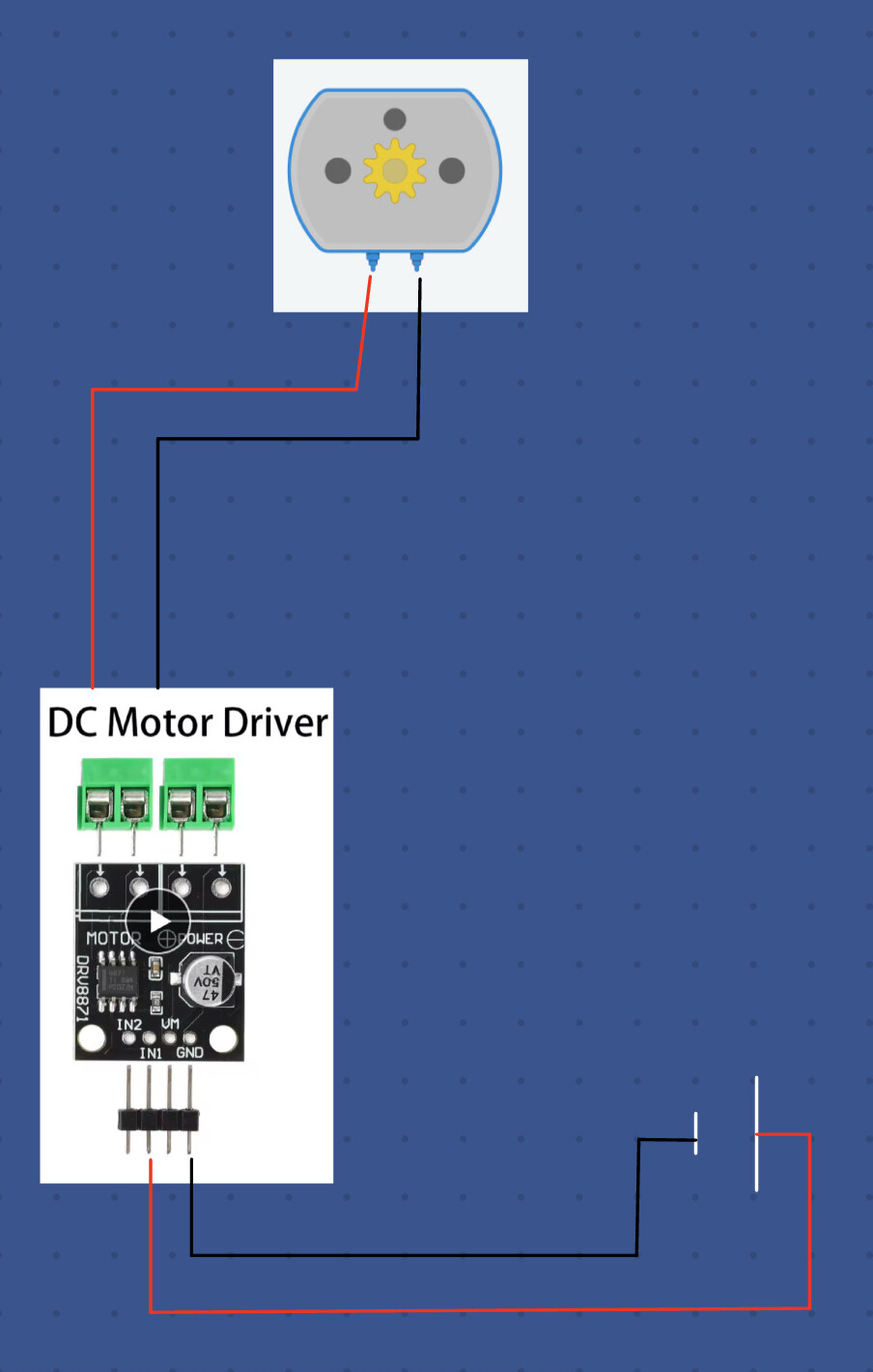
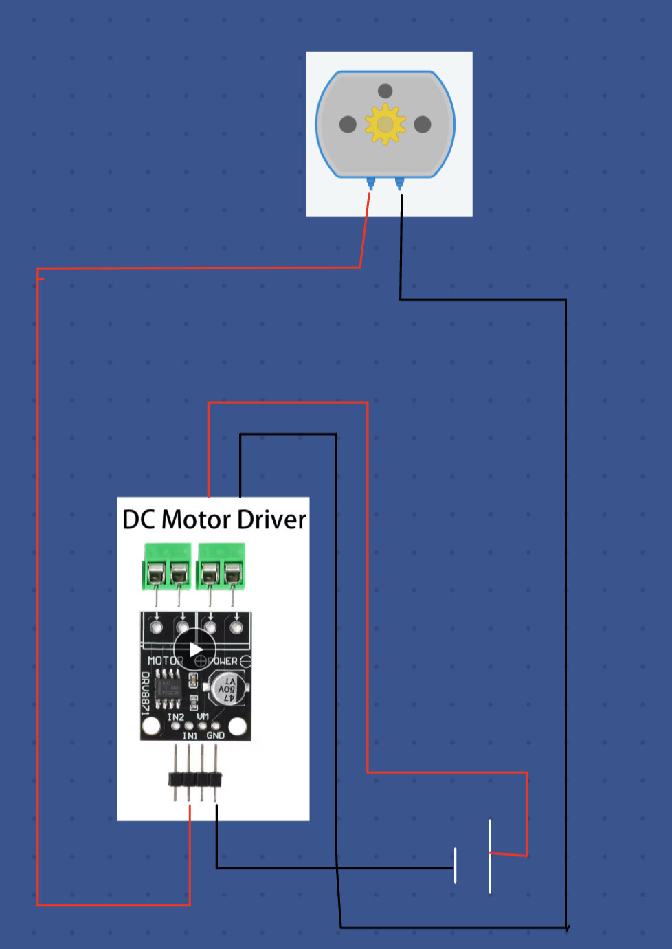
in your images, the board has 2 green screw terminal connectors at the top and a header at the bottom.
the motor should be connected to the top left connector. the image below shows that it is marked "MOTOR". the 12V power should be connected to the top right connector, the image below shows the + and - terminals
i'm suggesting that use a wire to connect the VM pin to either IN1 or IN2 and see if the motor runs. it should run in one direction when VM feeds IN1 and run in the opposite directioin when it feeds IN2
const int IN1pin =9;
const int IN2pin =10;

void setup (){
    pinMode (IN1pin,OUTPUT);
    pinMode (IN2pin,OUTPUT);
    randomSeed (analogRead (A0));
}


void loop (){
    //random.driection.0=forward,1=reverse
    int direction = random (0,2);

    //random speed 75 to 255 PWM
    int speed = random (75,256);

    //random duration 1 to 3 seconds
    int duration = random (1000,3001);

    //set motor direction and speed
    if (direction == 0){
        analogWrite  (IN1pin, speed);
        digitalWrite (IN2pin, LOW);
    } else{
        digitalWrite (IN1pin, LOW);
        analogWrite  (IN2pin, speed);
    }

    // motor run delay
    delay (duration);

    //stop motor
    digitalWrite (IN1pin, LOW);
    digitalWrite (IN2pin, LOW);

    // Pause before next cycle
    delay (1000);
}
No luck compiling? Or no luck getting the motor to run? What does that mean? Maybe take a look at the corrected codes.
Here is my very basic understanding of PWM…My understanding is that analog writing to a (PWM!) digital pin briefly turns that pin on and off (high and low) at a specific given interval. It is not partly on or off. It is either on or off, but pulsed extremely quickly. The load (motor, light, etc…) responds with the average of the impulses. The analog number written determines the duty cycle, or length of time the pin is on or off.
define that…Small means different things to different people.
const.int.IN1pin shouldn't have those dots, it should be const int IN1pin
void.setup() shouldn't have a dot
randomSeed (analogRead (AO)); should be A0 (A zero) not A letter O
i believe int duration = random (0,2); was indended to be int direction because `direction is underfined
INpin1 and INpin2 should be IN1pin and IN2pin
int duration = random (0,2);
after the above errors are corrected, the following occur
C:\stuff\SW\Arduino\_Others\Tst\Tst.ino: In function 'void setup()':
Tst:7:29: error: 'AO' was not declared in this scope
     randomSeed (analogRead (AO));
                             ^~
C:\stuff\SW\Arduino\_Others\Tst\Tst.ino:7:29: note: suggested alternative: 'A7'
     randomSeed (analogRead (AO));
                             ^~
                             A7
C:\stuff\SW\Arduino\_Others\Tst\Tst.ino: In function 'void loop()':
Tst:19:9: error: redeclaration of 'int duration'
     int duration = random (1000,3001);
         ^~~~~~~~
C:\stuff\SW\Arduino\_Others\Tst\Tst.ino:13:9: note: 'int duration' previously declared here
     int duration = random (0,2);
         ^~~~~~~~
Tst:22:9: error: 'direction' was not declared in this scope
     if (direction == 0){
         ^~~~~~~~~
C:\stuff\SW\Arduino\_Others\Tst\Tst.ino:22:9: note: suggested alternative: 'duration'
     if (direction == 0){
         ^~~~~~~~~
         duration
Tst:23:23: error: 'INpin1' was not declared in this scope
         analogWrite  (INpin1, speed);
                       ^~~~~~
C:\stuff\SW\Arduino\_Others\Tst\Tst.ino:23:23: note: suggested alternative: 'IN2pin'
         analogWrite  (INpin1, speed);
                       ^~~~~~
                       IN2pin
Tst:24:23: error: 'INpin2' was not declared in this scope
         digitalWrite (INpin2, LOW);
                       ^~~~~~
C:\stuff\SW\Arduino\_Others\Tst\Tst.ino:24:23: note: suggested alternative: 'IN2pin'
         digitalWrite (INpin2, LOW);
                       ^~~~~~
                       IN2pin
Tst:26:9: error: 'digtialWrite' was not declared in this scope
         digtialWrite (IN1pin, LOW);
         ^~~~~~~~~~~~
C:\stuff\SW\Arduino\_Others\Tst\Tst.ino:26:9: note: suggested alternative: 'digitalWrite'
         digtialWrite (IN1pin, LOW);
         ^~~~~~~~~~~~
         digitalWrite
Tst:34:19: error: 'INpin1' was not declared in this scope
     digitalWrite (INpin1,LOW);
                   ^~~~~~
C:\stuff\SW\Arduino\_Others\Tst\Tst.ino:34:19: note: suggested alternative: 'IN2pin'
     digitalWrite (INpin1,LOW);
                   ^~~~~~
                   IN2pin
exit status 1
'AO' was not declared in this scope
I admittedly did not read the code until just now. I see other issues besides the typos etc…
Make sure you did not burn up your motor. You are using a 12 volt power supply in post one. In post #15 you state the motor is a 6 volt motor.
My experience with PWM motor control and the drv8871 (or several other drivers) is that the motor will only respond down to a certain value. I think 75 is WAY to low to get the motor spinning. It might run at that value but likely needs to be briefly kick started at a higher value.
I think, after making sure your motor is not burned up, start with a much simpler code of just trying to get it to run in one direction at full speed and work your way up from there. Or the code in post #6 looks like it might work.
And by the way, if you are driving the 6 volt motor with a 12 volt supply, the 6 volt motor is still seeing the effect of approximately 8.52 volts if you are analog writing a value of 75 to the enable pin. So I suppose that should certainly have it spinning!!
And also…what exactly is your power supply? If it is a battery (car type or sealed lead acid among others) there is a good chance you might be sending more than 12 volts through the VIN pin on the nano AND the motor driver. Thus the motor at full speed.
I don’t remember exactly how I did it, but I blew the top half of the atmega chip off of an arduino uno with a car type battery. It was impressive! I don’t remember if I hooked it up backwards or if it was to much voltage. But now, if using a battery like that, I run it through a reverse polarity protected buck converter to lower the voltage down.
Yeah, tidy up the code, check the components over, and start simple.