Hey, I'm new to Arduino and want to know if it's possible to make a speedometer with a rotary encoder and a 7 segment 4 digit display? I want to replace my broken speedometer in my car with this by hooking the speedometer cable to the rotary encoder. If this is possible could someone give me some code to fiddle about with?
I reckon you would find it a lot simpler to put a magnet on a drive shaft and read its rpm with a coil, or some sort of Hall effect device just like any other car, rather than messing about with the cable end. Another option is to put a GPS module on the Uno instead, thereby avoiding getting under the car.
Definitely doable but I wouldn't use an encoder. You don't need a quadrature variant since you care about speed, not velocity and you don't need the resolution they typically come with. You also don't need another thing with bearings to wear out etc.
Consider finding a way to attach a small toothed wheel (e.g. a flat-disc with evenly spaced "teeth") like this:
Front wheel drive or rear wheel drive? What rotating drive train components do you have access to? You might simply paint white spots on the inside of a rear tire and then have one of the IR object detector modules detect the spot or spots as they go past the sensor.
Railroader:
Hall sensor would likely withstand the environment a bit better.
Indeed, and I guess that's why cars have them. My 1984 Fairlane read the drive shaft. I don't suppose it was the first to do so. It surely beats the hell out painting spots on the tyre.
I understand BMW use an ABS wheel sensor to feed the speedo. This may be common practice.
Sounds like you envisage driving the encoder shaft by the cable. I think that would be a rather awkward mechanism. Do encoders output continuous values or discrete values?
I've explored both GPS fed and HE fed methods. Both work. Each has its pros and cons.
The Hall Effect sensor and magnet have been fitted on my car for 9 months. Deadly accurate and repeatable and never misses a beat. Have survived thousands of km of city and country driving without needing a single adjustment. I'm amazed at that.
LED display works best of all display types -- so easy to read with the quickest of glances. Better than car's speedo.
Without your car's speedo working, you'll have to find a way to calibrate your creation.
A desktop simulation setup is essential.
If your car is post 2002, I think it will be equipped with an OBD II connection. This provides speed. (I now see you've told us that yr car is a 1983 Volvo, so skip this bit.)
Good luck. Lots of interesting technology you'll be learning about.
Guys in #7 and #8, read OP's Answer in #6. Volvo 1985....
GPS speedometers works well in open terrain but works badly when the road is surrounded by trees, maybe even wet trees…
Railroader:
Guys in #7 and #8, read OP's Answer in #6. Volvo 1985....
GPS speedometers works well in open terrain but works badly when the road is surrounded by trees, maybe even wet trees…
Why do you think that my suggestion is wrong.
Just because it says GM sensor doesn't mean that It will only work on a GM vehicle.
Might have to get a little creative to make it work, but it would probably be better than some homemade encoder.
It is simply a hall effect pulse generator.
If you look on E-Bay there are other speedo sensors besides the GM ones.
Might even get lucky and find one that would thread right on to the Volvo speedo drive on the transmission.
On my hot rod I have have a Stewert Warner drive with a GM offset adapter on a Toyota transmission. They all had the same threads and square drive.
Sometimes all it takes is a little research.
It's a Volvo 1985 and not GM even if similarities do exist. Volvo used German stuff in their cars. I doubt a Volvo 1985 even had ABS brakes. I was set to make en FMEA on an ABS unit 1989 before launching Volvo 850 I think it was. The ABS was the German Bosch.
I admit that I didn't do any Googling Before Writing.
Calibraring a home made speedo is no problem. Use a GPS on a road having the free sky above it.
Scratching my memory i find opto devices were used to sense the gear shift on the 4 gear manual gearbox. They were built in under the rubber couver around the stick and never clogged up with dirt. Well protected I could think of an opto solution despite my recommendation for Hall sensors.
Sensor has no idea if it's a Volvo or a GM. I have found that most of the gear driven speedo drives have the same thread and square drive. Have to do a little thinking outside the box.
Which LED colour works the best in the difficult situations like sunshine from from behide and side? I would put a bet on red. To use this meter for real I would suggest that You measure the incoming light and adjust the LED brightness accordingly. You don't want to see a boosted LED at maximum power driving in the dark.
Having owned a couple of Volvo 240s from the 80's & worked on a few more I'll step in with the following tidbit. Most if the 80's 240s use an electronic speedometer with the pickup being a VR (Variable Reluctance) sensor in the differential. I don't have a care to throw a scope & see what the output looks like so I can't help there.
I've tried white, blue and yellow (more like orange). All work. My preference is white as I always wear dark glasses driving. It's crisp. Red would be okay.
It has to be in deep shade -- just isn't readable in sunshine. I made a 3D printed hood. Inside this it works well and looks good.
You're right about being too bright at night, especially white. A light sensor and auto dimming is a good idea.
I've been using this on my car n one form or another for nine months, so the sensor side is well bedded in. It's a Hall Effect sensor and magnet. I did use GPS initially which has some advantages (and some disadvantages) and am developing a well finished unit using GPS.
Something that surprised me is how effective the speed display is compared to the car's analogue speedo. I never would have thought that reading the car's speedo was a time-consuming task, but it is. With the briefest of glances at the LED display I know the speed.
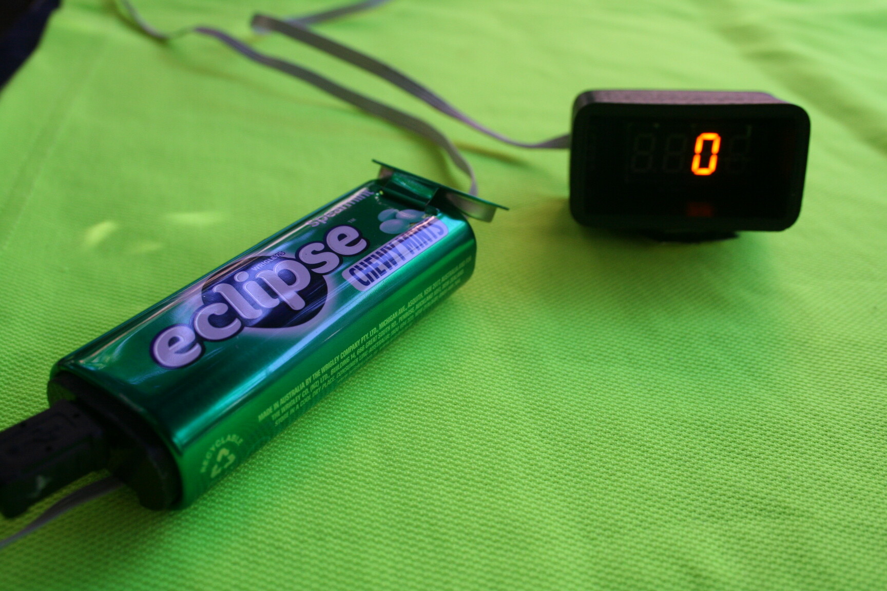
A couple of pics below. The electronics package is inside the mints tin.
Oh, I tapped the spike on the low side of the ignition coil, did some signal treatment and use an opto coupler. I made a device telling which gear was in use. Combining those two I could calculate and show the when the clutch was released….. That car was a SAAB 90 from year 1985...
The LED was bought from Poly Pacs USA having rather small red 7 segment LED that had very bright segments. I Think the were called MAN-1. Some 30 years ago….