Yes.
FSYNC is called SS on the arduino and is pin 10 on the nano (though you could use any spare digital pin for this but this pin (10) must be set to output for SPI to work how you want.).
SCLK is called SCK on arduino and is pin 13 (you must use this pin for hardware SPI).
SDATA is called MOSI on arduino and is pin 11 (you must also use this pin for hardware SPI).
Have a look here for pin mapping of nano.
Look here for details of SPI library.
VT91:
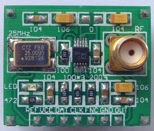
What is REF? I cannot read the IC name on the circuit. It is too small. It was a mistake that I bought this module.
I cannot see REF on the image link you supplied and the AD9833 chip does not have a REF pin.
I will take a wild guess and assume it's pin 7 on the module (referring to your image) and it's a copy of the reference clock signal fed to the AD9833 from an onboard crystal oscillator. You don't need to connect this to anything if it is.
I am just curious about the REF pin in case I want to synchronize something with the AD9833 module's crystal.
For those who are working in a similar project:
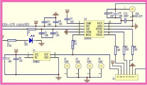
REF is connected to the output pin of the crystal, along with the MCLK of AD9833 (w/resistor)
The markings on the crystal read:

INTERQUIP
25.000
(pin 1 marker dot) L11B

I looked through INTERQUIP's website and found nothing with the code L11B. Maybe I cannot read the markings correctly.
Did you alter the code to put FSYNC on pin 9 instead of the defined pin 2 in the sketch or move the FNC wire to pin 2. The sketch uses pin 9 as master clock output so cannot be used as FSYNC (SS) pin.
You will not want the MCLK signal (pin 9) as your module has an onboard clock source so does not need one from the Arduino.
EDIT: Also your frequency calculations may be wrong as the sketch is basing them on a 1MHz clock and it appears your module has a 25MHz clock source.
VT91:
Is FSYNC(SS) used only to synchronize clocks for the serial communication or as the general clock source of AD9833?
Neither, FSYNC is what is called SS in arduino land and needs pulling low before any SPI data is sent to the AD9833.
So I should change my code not to include the SS pin at all? Neither as pin 9 nor as pin 2.
If you do not alter the code you linked too then the FSYNC wire you have on pin 9 in the picture should be put on pin 2 and pin 9 does not need connecting at all.
Riva:
If you do not alter the code you linked too then the FSYNC wire you have on pin 9 in the picture should be put on pin 2 and pin 9 does not need connecting at all.
Where in the code are the pin configurations, besides the comments at the beginning of the program?
Thank you.
/*
AD9837 Pro Generator sample code
This was written in Arduino 1.0.1,
for an Arduino Pro Mini, 5V, 16MHz
Pete Dokter, 9/2/12
Remixed by Anne Mahaffey, 10/8/12
ReRemixed by sinneb, 15th of april 2013

The connections to the AD9837 board are:

FSYNC -> 2
SCLK -> 13 (SCK)
SDATA -> 11 (MOSI)
MCLK -> 9 (Timer1)
+Vin = VCC on Pro Micro
GND -> GND

This code bears the license of the beer. If you make money off of this,
you gotta beer me.
*/

long freq; //32-bit global frequency variable

#include <SPI.h>
#include "TimerOne.h"

// Define the FSYNC (used for SD funtion)
#define FSYNC 2

void setup()
{
 Timer1.initialize(1);
 Timer1.pwm(9, 512);

 pinMode(FSYNC, OUTPUT); //FSYNC

 Serial.begin(9600); // start serial communication at 9600bps

 digitalWrite(FSYNC, HIGH);

 SPI.setDataMode(SPI_MODE2); // requires SPI Mode for AD9837
 SPI.begin();

 delay(100); //A little set up time, just to make sure everything's stable

 //Initial frequency
 freq = 4000;
 WriteFrequencyAD9837(freq);

 Serial.print("Frequency is ");
 Serial.print(freq);
 Serial.println("");

}

void loop()
{

}
void WriteFrequencyAD9837(long frequency)
{
 //
 int MSB;
 int LSB;
 int phase = 0;

 //We can't just send the actual frequency, we have to calculate the "frequency word".
 //This amounts to ((desired frequency)/(reference frequency)) x 0x10000000.
 //calculated_freq_word will hold the calculated result.
 long calculated_freq_word;
 float AD9837Val = 0.00000000;

 AD9837Val = (((float)(frequency))/16000000);
 calculated_freq_word = AD9837Val*0x10000000;

 /*
 Serial.println("");
 Serial.print("Frequency word is ");
 Serial.print(calculated_freq_word);
 Serial.println("");
 */

 //Once we've got that, we split it up into separate bytes.
 MSB = (int)((calculated_freq_word & 0xFFFC000)>>14); //14 bits
 LSB = (int)(calculated_freq_word & 0x3FFF);

 //Set control bits DB15 ande DB14 to 0 and one, respectively, for frequency register 0
 LSB |= 0x4000;
 MSB |= 0x4000;

 phase &= 0xC000;

 WriteRegisterAD9837(0x2100);

 //delay(500);

 //Set the frequency==========================
 WriteRegisterAD9837(LSB); //lower 14 bits

WriteRegisterAD9837(MSB); //upper 14 bits

WriteRegisterAD9837(phase); //mid-low

 //Power it back up
 //AD9837Write(0x2020); //square
 WriteRegisterAD9837(0x2000); //sin
 //AD9837Write(0x2002); //triangle

}

//This is the guy that does the actual talking to the AD9837
void WriteRegisterAD9837(int dat)
{
 digitalWrite(FSYNC, LOW); //Set FSYNC low
 delay(10);

 SPI.transfer(highByte(dat)); Serial.println(highByte(dat));
 SPI.transfer(lowByte(dat)); Serial.println(lowByte(dat));

delay(10);
 digitalWrite(FSYNC, HIGH); //Set FSYNC high
}
Riva:
EDIT: Also your frequency calculations may be wrong as the sketch is basing them on a 1MHz clock and it appears your module has a 25MHz clock source.
1Mhz or 16 Mhz ?
Does the hex number constant 0X**10,**000,000 represent 1 Mhz
or
does the 16,000,000 reference frequency represent 16 Mhz clock source
that was used by the author of this code?
 //We can't just send the actual frequency, we have to calculate the "frequency word".
 //This amounts to ((desired frequency)/(reference frequency)) x 0x10000000.
 //calculated_freq_word will hold the calculated result.
 long calculated_freq_word;
 float AD9837Val = 0.00000000;

 AD9837Val = (((float)(frequency))/16000000);
 calculated_freq_word = AD9837Val*0x10000000;
VT91:
Where in the code are the pin configurations, besides the comments at the beginning of the program?
setup() defines the FSYNC pin (2) as output but the other SPI pins are hardware dependent and in the case of the UNO are pins 10-13. When SPI.begin() is called in setup() it sets these pins up as needed.
Riva:
EDIT: Also your frequency calculations may be wrong as the sketch is basing them on a 1MHz clock and it appears your module has a 25MHz clock source.
1Mhz or 16 Mhz ?
Neither, 25MHz as you said in a previous post the clock chip on the AD9833 module had 25.000 etched into its surface.
I said 1MHz because the sinneb link says...
I added the Timer1 library to generate the masterclock for the AD9833. This clock runs in the background at ~1Mhz and is made available through pin 9.
Does the hex number constant 0X**10,**000,000 represent 1 Mhz
or
does the 16,000,000 reference frequency represent 16 Mhz clock source
that was used by the author of this code?
I am not familiar with the Timer1 library used but what the sinneb author wrote above about 1MHz clock does not match the calculation used in the sketch. Either the calculation is wrong as it's done for a 16MHz clock or the comment is incorrect or I'm more stupid than I thought.
//We can't just send the actual frequency, we have to calculate the "frequency word".
//This amounts to ((desired frequency)/(reference frequency)) x 0x10000000.
//calculated_freq_word will hold the calculated result.
long calculated_freq_word;
float AD9837Val = 0.00000000;
For your module you would do AD9837Val = (((float)(frequency))/25000000);, the calculated_freq_word = AD9837Val*0x10000000; stays the same as it's just making the floating point number suitable for the chip.
Out of curiosity I bought a AD9833 module (see picture) and cobbled together some code to test it that is attached to this post. I hooked it up to a mega as per pinout in sketch and tested various frequencies using DSO scope that could only handle upto 4MHz. Hope this is of some help.
Dear Riva, thank you very much for your help.
I got everything to work now.
Everything works perfectly.
Maybe there will be some code interference in the future, but I hope not.
I am using a text LCD screen and an AD9833.
Riva:
Out of curiosity I bought a AD9833 module (see picture) and cobbled together some code to test it that is attached to this post. I hooked it up to a mega as per pinout in sketch and tested various frequencies using DSO scope that could only handle upto 4MHz. Hope this is of some help.
hi
i use this code to run ad9833 with mega2560. but i just have sin. wave with a constant frequency.
what is the mistake? :o
mojzare70:
hi
i use this code to run ad9833 with mega2560. but i just have sin. wave with a constant frequency.
what is the mistake? :o
IIRC the example sketch I wrote only outputs a fixed frequency.
Try changing double freq = 4000.0; to a different values and see if the frequency changes.
Riva:
IIRC the example sketch I wrote only outputs a fixed frequency.
Try changing double freq = 4000.0; to a different values and see if the frequency changes.
Hi Riva,
First off, I'd like to thank-you for taking the time to share this code(most excellent!). As I've successfully implemented it in my own project.
That said, can you help figure out a way to fine tune the frequencies to the second or third decimal for lower frequencies? I tried with the existing code, but it doesn't appear to adjust the frequency beyond the first decimal no matter what I put in the double freq =

