Hello,
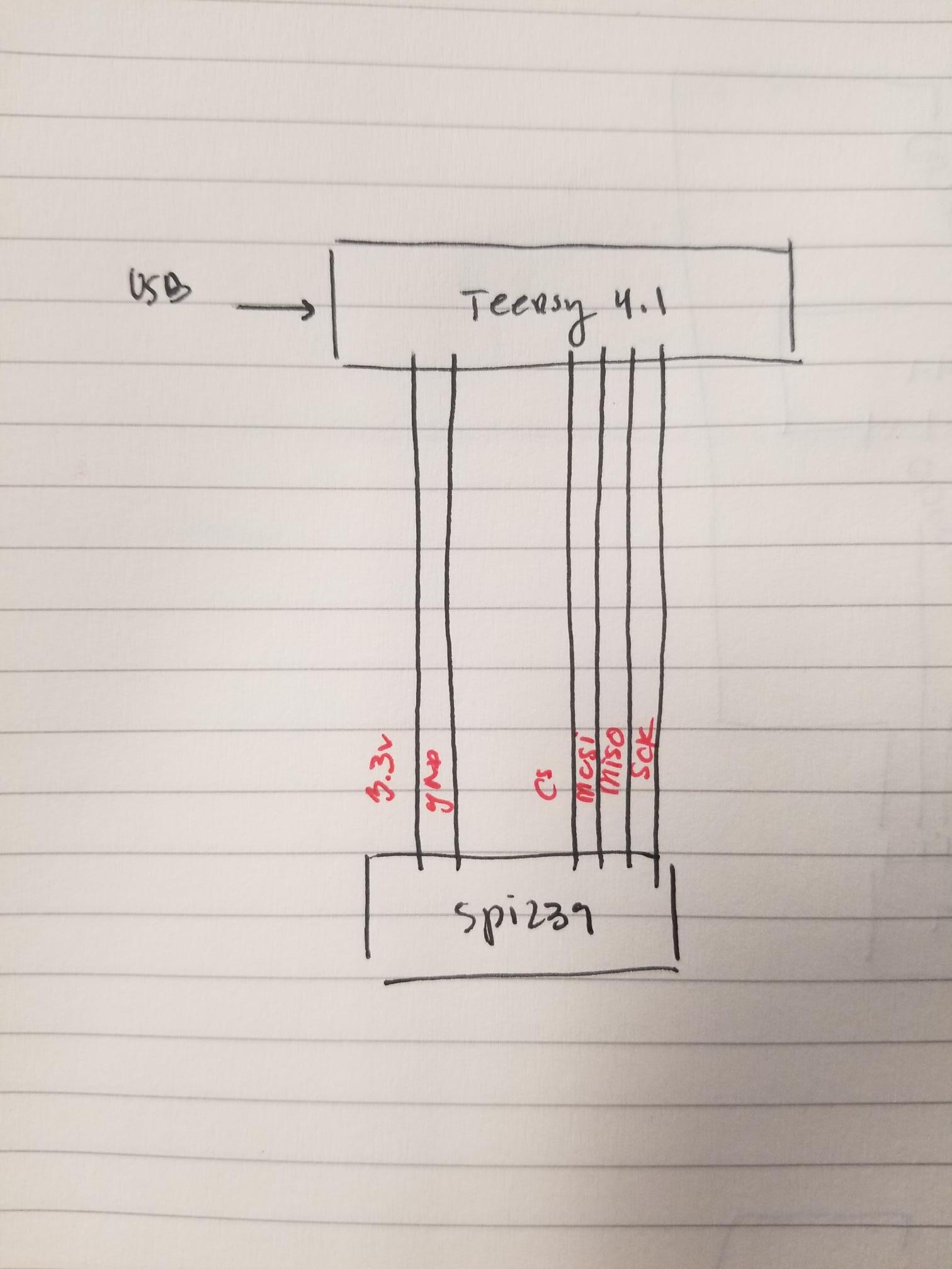
I have been using the INA239 current sensor via SPI to a Teensy4.1 board successfully with a wire length of about 5 inches. The strange thing is that, if I extend the wire length to 12 inches, I can see on the oscilloscope that the MOSI line stops working and stays relatively low voltage around 1.8 volts when my power is 3.3V. I then get nothing from the SPI communication after that.
The datasheet for the INA239 states that the data is shifted out on the Rising edge and data is sampled on the Falling edge, and I believe I have the settings correct.
SPISettings INA239_settings(1000000, MSBFIRST, SPI_MODE1);
Any thoughts on why the MOSI line dies down after adding 7 inches to the length of the wire?
The rest of my code is below:
/*
   MCU: TEENSY 4.1
   URL:
   https://www.pjrc.com/store/teensy41.html
   LEAP: INA239 Sensor for OUTPUT power
   DATASHEET:
   https://www.ti.com/lit/ds/symlink/ina239.pdf?ts=1684330883046&ref_url=https%253A%252F%252Fwww.ti.com%252Fproduct%252FINA239
*/

#include <Streaming.h>
#include <SPI.h>

#define CS          10

#define POT_MAX     255


/*
   SHUNT_CAL = (819.2x10^(6))*(Current_LSB)*(Rshunt)

   CURRENT_LSB = (max Current expected)/(2^(15))

   CURRENT[A] = (CURRENT_LSB)*(CURRENT_FROM_REGISTER)

   POWER[W] = (0.2)*(CURRENT_LSB)*(POWER_FROM_REGISTER)

   R_SHUNT = 1.365 milliOhms -> 100milliV reading range

*/

//const double current_lsb = 0.001068115; // 1.365 milli ohm
const double current_lsb = 0.0000305; // 25 milli ohm

int serialCount = 0;
float v1, v2, outv1, outv2;
byte pc1, pc2, outpc1, outpc2;
float currentSum = 0;
float mappedVoltage = 0;
float voltage, current;
double power;
float outvoltage, outcurrent, outpower;

/*
    INA239 captures data on falling edge & shifts out data on rising edge.
    Therefore we need to use SPI_MODE1.
    spi settings from the spi.h online (speedMax in hz, dataOrder, dataMode)
*/

SPISettings INA239_settings(1000000, MSBFIRST, SPI_MODE1);

void setup() {

  pinMode(CS, OUTPUT);
  digitalWrite(CS, HIGH); // turn spi device 1 off initially

  Serial.begin(115200);
  SPI.begin();

//  while (!Serial) {
//    ; // wait for serial port to connect. Needed for native USB port only
//  }
}

float mapf(float x, float in_min, float in_max, float out_min, float out_max) {
  /* mapping values: analog to ____ */
  return (x - in_min) * (out_max - out_min) / (in_max - in_min) + out_min;
}

/*
   function to write calibration value based on the shunt resistor used.
   must transder to register in hexidecimal.
*/
void writeShuntCal() {
  SPI.beginTransaction(INA239_settings);
  digitalWrite(CS, LOW);              //turn on spi device 1
  //  SPI.transfer(0x01 << 2 | 0x00);   //ADC_CONFIG REGISTER
  //  SPI.transfer(0xB0);
  //  SPI.transfer(0x05);
  //  SPI.transfer16(0x07);
  SPI.transfer(0x02 << 2 | 0x00);  //SHUNT_CAL REGISTER; SET TO MEASURE <= 35A. OUTPUT SHUNT RESISTANCE: 1.365mOHM
  SPI.transfer(0x04);
  SPI.transfer(0xAE);
  //  SPI.transfer(0x01);
  //  SPI.transfer(0xF2);
  digitalWrite(CS, HIGH);
  SPI.endTransaction();
}

/*
   function to read the sense voltage. register 5h
*/
void readVoltage() {
  SPI.beginTransaction(INA239_settings);
  digitalWrite(CS, LOW);            //turn on spi device 1
  SPI.transfer(0x05 << 2 | 0x01);   //register to read
  v1 = SPI.transfer16(0);
  voltage = v1 * (0.003125);
  Serial << "Voltage: " << voltage << endl;
  digitalWrite(CS, HIGH);           // turn off spi device 1
  SPI.endTransaction();
}

/*
   function to read the sense current. register 7h
*/
void readCurrent() {
  SPI.beginTransaction(INA239_settings);
  digitalWrite(CS, LOW);
  SPI.transfer(0x07 << 2 | 0x01);
  pc1 = SPI.transfer16(0x00);
  pc2 = SPI.transfer(0x00);
  currentSum = ((uint32_t)pc1 << 8 | pc2);
  current = (currentSum * current_lsb) * 2;
  //Serial << pc1 << " " << pc2 << endl;
  //Serial << currentSum << endl;
  Serial << "Current: " << current << endl;
//  if (current > 60) {
//    current = 0;
//    Serial << "Current: " << _FLOAT(current, 6) << endl;
//  }
//  else {
//    Serial << "Current: " << _FLOAT(current, 6) << endl;
//  }
  digitalWrite(CS, HIGH);
  SPI.endTransaction();
}

/*
   function to manually calculate power based on the
   value read from the voltage and current reg.
*/
void readPower_ManualCalculation() {
  power = (voltage * current);
  Serial << "power: " << power << endl;
}


/*
   function to read the sense power. register 8h
*/
void readPower() {
  SPI.beginTransaction(INA239_settings);
  digitalWrite(CS, LOW);
  SPI.transfer(0x08 << 2 | 0x01);
  byte p1 = SPI.transfer(0x00);
  byte p2 = SPI.transfer(0x00);
  byte p3 = SPI.transfer(0x00);
  power = ((uint32_t)p1 << 16 | (uint32_t)p2 << 8 | p3) * (0.2) * (0.001068115);
  Serial << "Power:   " << power << endl;
  digitalWrite(CS, HIGH);
  SPI.endTransaction();
}

/*
   function to read the voltage drop across the shunt resistor.
   register 4h
*/
void readShuntVoltage() {
  SPI.beginTransaction(INA239_settings);
  digitalWrite(CS, LOW);
  SPI.transfer(0x04 << 2 | 0x01);
  float shuntVoltage = SPI.transfer16(0);
  float shuntVoltageTwo = (shuntVoltage * 0.000005);
  Serial << shuntVoltage << endl;
  Serial << _FLOAT(shuntVoltageTwo, 6) << endl;
  digitalWrite(CS, HIGH);
  SPI.endTransaction();
}

/*
   function to read the shunt calibration register.
   register 2h
*/
void readShuntCalReg() {
  SPI.beginTransaction(INA239_settings);
  digitalWrite(CS, LOW);
  SPI.transfer(0x02 << 2 | 0x01);
  float shunt = SPI.transfer16(0);
  //byte shuntAdd1 = SPI.transfer(0x00);
  //byte shuntAdd2 = SPI.transfer(0x00);
  //Serial << shuntAdd2 << " " << shuntAdd1 << endl;
  Serial << shunt << endl;
  digitalWrite(CS, HIGH);
  SPI.endTransaction();
}

/*
   function to read the ADC range mode. register 1h
   Two options only with the INA239.
   1. +- 163.84 mV
   2. +- 40.96 mV
*/
void readADCReg() {
  SPI.beginTransaction(INA239_settings);
  digitalWrite(CS, LOW);
  SPI.transfer(0x01 << 2 | 0x01);
  float adcReg = SPI.transfer16(0);
  Serial << adcReg << endl;
  digitalWrite(CS, HIGH);
  SPI.endTransaction();
}

/*
   function to read the manufacturer ID. register 3Eh
   should read 84 73 -> =
*/
void readID() {
  SPI.beginTransaction(INA239_settings);
  digitalWrite(CS, LOW);
  SPI.transfer(0x3E << 2 | 0x01);
  byte m1 = SPI.transfer(0x00);
  byte m2 = SPI.transfer(0x00);
  Serial << m1 << " " << m2 << endl;
  digitalWrite(CS, HIGH);
  SPI.endTransaction();
}

void setAD5160Resistance(byte value) {
  /*--- Function to set the resistance value on the AD5160 ---*/
  digitalWrite(CS, LOW);      // Select the AD5160
  //SPI.transfer(0x11);                         // Command byte to update the resistance
  SPI.transfer(value);                        // Send the value to set the resistance (0 to POT_MAX)
  digitalWrite(CS, HIGH);     // Deselect the AD5160
}

int readAD5160Resistance() {
  /*--- Function to read the current resistance value from the AD5160 ---*/
  digitalWrite(CS, LOW);         // Select the AD5160
  SPI.transfer(0x01);                                   // Command byte to read the resistance
  byte value = SPI.transfer(0x00);                      // Dummy byte to read the response
  digitalWrite(CS, HIGH);        // Deselect the AD5160
  return map(value, 0, POT_MAX, 0, 10000); // Map to the desired resistance range
}

/*
*/
void loop() {
  delay(500);
  writeShuntCal();
  //readShuntCalReg();
  //readADCReg();
  readID();
  //readShuntVoltage();
  Serial << "----------------------------" << endl;
  readVoltage();
  readCurrent();
  //readPower();
  readPower_ManualCalculation();
  Serial << "----------------------------" << endl;
}