SPI Full Duplex (Professional Code Error)

Hi All

As many will know from reading my previous posts Im trying to achieve full duplex communication, no one seems to know how to write this code for arduino or at least not willing to, so i hired a professional to write the code example for me that i could integrate into my project.

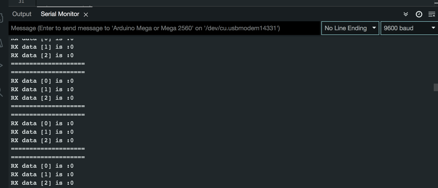
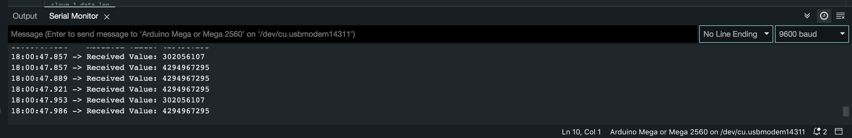
Well that was a complete waste of time, below is the code i got, it doesn't work , just get random junk data, however this is the closest code i have to achieving my goal.

Just to give you a heads up before you read the code, my requirements provided to a professional are as attached.

Project Details.pdf (89.5 KB)

Hoping someone here can see the issue and advise on how to correct it.

Master Code

#include <Arduino.h>
#include <SPI.h>

#define SLAVE_1_CS 1
#define SLAVE_2_CS 2
#define SLAVE_3_CS 3
#define SLAVE_4_CS 4

#define RESPONSE_LENGTH 4  //bytes

byte S1_data_out[] = { 0, 0, 0 };
byte S2_data_out[] = { 0, 0, 0 };
byte S3_data_out[] = { 0, 0, 0 };
byte S4_data_out[] = { 0, 0, 0 };

byte S1_data_in[] = { 0, 0, 0, 0 };
byte S2_data_in[] = { 0, 0, 0, 0 };
byte S3_data_in[] = { 0, 0, 0, 0 };
byte S4_data_in[] = { 0, 0, 0, 0 };

void setup() {
  Serial.begin(9600);
  SPI.begin();
  pinMode(SLAVE_1_CS, OUTPUT);
  pinMode(SLAVE_2_CS, OUTPUT);
  pinMode(SLAVE_3_CS, OUTPUT);
  pinMode(SLAVE_4_CS, OUTPUT);
  digitalWrite(SLAVE_1_CS, HIGH);
  digitalWrite(SLAVE_2_CS, HIGH);
  digitalWrite(SLAVE_3_CS, HIGH);
  digitalWrite(SLAVE_4_CS, HIGH);
}

void loop() {
  S1_data_out[0] = 0;
  S1_data_out[1] = 0;
  S1_data_out[2] = 0;
  Slave_1_tr(S1_data_out, 3);                     //send content of packet length 3, and recieve its data
  print_response(S1_data_in, RESPONSE_LENGTH);  //print data whose length is slave_1_data_len

  S2_data_out[0] = 0;
  S2_data_out[1] = 0;
  S2_data_out[2] = 0;
  Slave_2_tr(S2_data_out, 3);
  print_response(S2_data_in, RESPONSE_LENGTH);

  S3_data_out[0] = 0;
  S3_data_out[1] = 0;
  S3_data_out[2] = 0;
  Slave_3_tr(S3_data_out, 3);
  print_response(S3_data_in, RESPONSE_LENGTH);

  S4_data_out[0] = 0;
  S4_data_out[1] = 0;
  S4_data_out[2] = 0;
  Slave_4_tr(S4_data_out, 3);
  print_response(S4_data_in, RESPONSE_LENGTH);
}

void Slave_1_tr(uint8_t *Data_to_send, uint8_t command_length) {
  digitalWrite(SLAVE_1_CS, LOW);

  // uint8_t response_len = SPI.transfer(command_length);

  // uint8_t receivedData[response_len];

  for (int i = 0; i < RESPONSE_LENGTH; i++) {
    S1_data_in[i] = SPI.transfer(i < command_length ? Data_to_send[i] : 0x0);
  }

  digitalWrite(SLAVE_1_CS, HIGH);

  // memcpy(response_data, receivedData, response_len);

  // return response_len;
}

void Slave_2_tr(uint8_t *Data_to_send, uint8_t command_length) {
  digitalWrite(SLAVE_2_CS, LOW);

  // uint8_t response_len = SPI.transfer(command_length);

  // uint8_t receivedData[response_len];

  for (int i = 0; i < RESPONSE_LENGTH; i++) {
    S2_data_in[i] = SPI.transfer(i < command_length ? Data_to_send[i] : 0x0);
  }

  digitalWrite(SLAVE_2_CS, HIGH);

  // memcpy(response_data, receivedData, response_len);

  // return response_len;
}

void Slave_3_tr(uint8_t *Data_to_send, uint8_t command_length) {
  digitalWrite(SLAVE_3_CS, LOW);

  // uint8_t response_len = SPI.transfer(command_length);

  // uint8_t receivedData[response_len];

  for (int i = 0; i < RESPONSE_LENGTH; i++) {
    S3_data_in[i] = SPI.transfer(i < command_length ? Data_to_send[i] : 0x0);
  }

  digitalWrite(SLAVE_3_CS, HIGH);

  // memcpy(response_data, receivedData, response_len);

  // return response_len;
}

void Slave_4_tr(uint8_t *Data_to_send, uint8_t command_length) {
  digitalWrite(SLAVE_4_CS, LOW);

  // uint8_t response_len = SPI.transfer(command_length);

  // uint8_t receivedData[response_len];

  for (int i = 0; i < RESPONSE_LENGTH; i++) {
    S4_data_in[i] = SPI.transfer(i < command_length ? Data_to_send[i] : 0x0);
  }

  digitalWrite(SLAVE_4_CS, HIGH);

  // memcpy(response_data, receivedData, response_len);

  // return response_len;
}

void print_response(uint8_t *data, uint8_t length) {
  // Serial.println("Received  ");
  // Serial.print("Bytes: ");
  // for (uint8_t i = 0; i < length; i++) {
  //   Serial.print(data[i], HEX);
  // }
  // Serial.println("");

  uint32_t combinedValue = (static_cast<uint32_t>(data[0]) << 24) | (static_cast<uint32_t>(data[1]) << 16) | (static_cast<uint32_t>(data[2]) << 8) | static_cast<uint32_t>(data[3]);
  Serial.print("Received Value: ");
  Serial.println(combinedValue);
}

Slave Code

#include <Arduino.h>
#include <SPI.h>

uint8_t txData[] = { 0, 0, 0, 0 };
uint8_t rxData[4];
volatile bool flag = false;
volatile int index = 0;

void setup() {
  Serial.begin(9600);
  pinMode(SS, INPUT_PULLUP);
  pinMode(MISO, OUTPUT);
  bitClear(SPCR, MSTR);   //board is Slave
  bitSet(SPCR, SPE);      //SPI Port is created
  SPI.attachInterrupt();  //LIE, GIE are active
}

void loop() {
  preparedata();
  if (flag == true) {
    noInterrupts();  //critical section
    interrupts();
    Serial.println("====================");
    for (int i = 0; i < 4; i++) {
      Serial.println("RX data [" + String(i) + "] is :" + String(rxData[i]));
    }
    Serial.println("====================");
    flag = false;
  }
}

ISR(SPI_STC_vect) {
  rxData[index] = SPDR;
  SPDR = txData[index];
  index++;
  if (index >= 4) {
    index = 0;
    flag = true;
  }
}

void preparedata() {
  uint32_t value = 0xABCD1234;  // 32-bit value

  txData[0] = (value >> 24) & 0xFF;  // Most significant byte (MSB)
  txData[1] = (value >> 16) & 0xFF;
  txData[2] = (value >> 8) & 0xFF;
  txData[3] = value & 0xFF;  // Least significant byte (LSB)
}

More homedepot "professional" it seams. What did you pay for the code that does not have a receiving part built in (just talking about master code, did not bother to read the slave).

See image in attachment, post#1.

@caller890 The image is incomplete, as ground is not shown connecting the units. Please advise what the power setup is for all units(one power supply, or more? Grounding, etc.), or update the drawing.

I havent paid for it yet, as it not working but $275 thats in escro account, which probably will come back to me , so anyone can get it to work , i have $275 for you lol

The ground is connected, i just never drew it on, i will get this updated. apologises

At moment all boards are powered via the USB as i have them all linked to computer for serial monitoring to debug.

I have commented out slaves 2 - 4 and just working with one slave at moment , to much junk data to try fix with 4 slaves connected.

never mind. I really really hate the lag on this forum.

see edited reply above. I find this problem is getting worse, but it's not on topic.

1 Like

Ill update this and post a JPEG, the wiring is standard at the moment between two Ardunio Mega 2560, i have commended our slaves 2 - 4 at this present time. until i can get one slave to work, let alone 4.

GND - GND
MISIO - MISO - 50
MOSI - MOSI - 51
SLK - SLK - 52
CS - CS - 53

This is the code fresh for the pro that wrote it, all CS pins were changed to correct one, slave 1 CS 53, im receiving the bytes but the data is trash, ill post the serial print

53 on both master and slave 1

This is the slave, if i change the vales being transmitted to say 123, it makes no difference.

This is the master.

if i change the uint32_t value = 0xABCD1234; to a random number within 32bit range it makes no difference.

only slave 1 is connected to 53, i have commended out all code related to Slaves 2 - 4 , at moment im just trying to get slave 1 operational before i move onto Slave 2 - 4

Changed wiring to pin 5 on master and set this as CS and left slave as pin 53.

i know the wiring is correct as if i unplug the CS from the slave , it stops printing bytes on the serial monitor, as soon as i connect again , it starts again.

Yes sir

#define SLAVE_1_CS 5
// #define SLAVE_2_CS 2
// #define SLAVE_3_CS 3
// #define SLAVE_4_CS 4

it was set to 53 , i promise the code i posted on here was fresh off the email from the person that wrote it with instructions to change all CS pins to what i need

The code is defiantly not right, its a complex code , i have spent months trying to find someone that can write me an example that can send and receive data with different amount of bytes from the master to multiple slaves full duplex.

its driving me crazy, i have invested to much time and money on this project to give it up. somone must know how to write this code , SPI Full Duplex is so well documented about its abilities, but try find an example of it , its impossible .

Im willing to pay anyone for a working code, then once i have integrated into my project im willing to pay for debugging.

Ok updated code below, still getting the same results.

#include <Arduino.h>
#include <SPI.h>

#define SLAVE_1_CS 53
// #define SLAVE_2_CS 2
// #define SLAVE_3_CS 3
// #define SLAVE_4_CS 4

#define RESPONSE_LENGTH 4  //bytes

byte S1_data_out[] = { 0, 0, 0 };
// byte S2_data_out[] = { 0, 0, 0 };
// byte S3_data_out[] = { 0, 0, 0 };
// byte S4_data_out[] = { 0, 0, 0 };

byte S1_data_in[] = { 0, 0, 0, 0 };
// byte S2_data_in[] = { 0, 0, 0, 0 };
// byte S3_data_in[] = { 0, 0, 0, 0 };
// byte S4_data_in[] = { 0, 0, 0, 0 };

void setup() {
  Serial.begin(9600);
  SPI.begin();
  pinMode(SLAVE_1_CS, OUTPUT);
  // pinMode(SLAVE_2_CS, OUTPUT);
  // pinMode(SLAVE_3_CS, OUTPUT);
  // pinMode(SLAVE_4_CS, OUTPUT);
  digitalWrite(SLAVE_1_CS, HIGH);
  // digitalWrite(SLAVE_2_CS, HIGH);
  // digitalWrite(SLAVE_3_CS, HIGH);
  // digitalWrite(SLAVE_4_CS, HIGH);
}

void loop() {
  S1_data_out[0] = 1;
  S1_data_out[1] = 2;
  S1_data_out[2] = 3;
  Slave_1_tr(S1_data_out, 3);                     //send content of packet length 3, and recieve its data
  print_response(S1_data_in, RESPONSE_LENGTH);  //print data whose length is slave_1_data_len

  // S2_data_out[0] = 0;
  // S2_data_out[1] = 0;
  // S2_data_out[2] = 0;
  // Slave_2_tr(S2_data_out, 3);
  // print_response(S2_data_in, RESPONSE_LENGTH);

  // S3_data_out[0] = 0;
  // S3_data_out[1] = 0;
  // S3_data_out[2] = 0;
  // Slave_3_tr(S3_data_out, 3);
  // print_response(S3_data_in, RESPONSE_LENGTH);

  // S4_data_out[0] = 0;
  // S4_data_out[1] = 0;
  // S4_data_out[2] = 0;
  // Slave_4_tr(S4_data_out, 3);
  // print_response(S4_data_in, RESPONSE_LENGTH);
}

void Slave_1_tr(uint8_t *Data_to_send, uint8_t command_length) {
  digitalWrite(SLAVE_1_CS, LOW);

  // uint8_t response_len = SPI.transfer(command_length);

  // uint8_t receivedData[response_len];

  for (int i = 0; i < RESPONSE_LENGTH; i++) {
    S1_data_in[i] = SPI.transfer(i < command_length ? Data_to_send[i] : 0x0);
  }

  digitalWrite(SLAVE_1_CS, HIGH);

  // memcpy(response_data, receivedData, response_len);

  // return response_len;
}

// void Slave_2_tr(uint8_t *Data_to_send, uint8_t command_length) {
//   digitalWrite(SLAVE_2_CS, LOW);

//   // uint8_t response_len = SPI.transfer(command_length);

//   // uint8_t receivedData[response_len];

//   for (int i = 0; i < RESPONSE_LENGTH; i++) {
//     S2_data_in[i] = SPI.transfer(i < command_length ? Data_to_send[i] : 0x0);
//   }

//   digitalWrite(SLAVE_2_CS, HIGH);

//   // memcpy(response_data, receivedData, response_len);

//   // return response_len;
// }

// void Slave_3_tr(uint8_t *Data_to_send, uint8_t command_length) {
//   digitalWrite(SLAVE_3_CS, LOW);

//   // uint8_t response_len = SPI.transfer(command_length);

//   // uint8_t receivedData[response_len];

//   for (int i = 0; i < RESPONSE_LENGTH; i++) {
//     S3_data_in[i] = SPI.transfer(i < command_length ? Data_to_send[i] : 0x0);
//   }

//   digitalWrite(SLAVE_3_CS, HIGH);

//   // memcpy(response_data, receivedData, response_len);

//   // return response_len;
// }

// void Slave_4_tr(uint8_t *Data_to_send, uint8_t command_length) {
//   digitalWrite(SLAVE_4_CS, LOW);

//   // uint8_t response_len = SPI.transfer(command_length);

//   // uint8_t receivedData[response_len];

//   for (int i = 0; i < RESPONSE_LENGTH; i++) {
//     S4_data_in[i] = SPI.transfer(i < command_length ? Data_to_send[i] : 0x0);
//   }

//   digitalWrite(SLAVE_4_CS, HIGH);

//   // memcpy(response_data, receivedData, response_len);

//   // return response_len;
// }

void print_response(uint8_t *data, uint8_t length) {
  // Serial.println("Received  ");
  // Serial.print("Bytes: ");
  // for (uint8_t i = 0; i < length; i++) {
  //   Serial.print(data[i], HEX);
  // }
  // Serial.println("");

  uint32_t combinedValue = (static_cast<uint32_t>(data[0]) << 24) | (static_cast<uint32_t>(data[1]) << 16) | (static_cast<uint32_t>(data[2]) << 8) | static_cast<uint32_t>(data[3]);
  Serial.print("Received Value: ");
  Serial.println(combinedValue);
}

I sense you're frustrated. We are too.

The schematic must be updated with pin numbers that correctly reflect the code usage. This is why so often, threads on this forum are punctuated with repeated requests for full schematics. Note the number of messages wasted, just querying what pins are being used for what - this is all wasted bandwidth, and those who would help very quickly tire of making these repeated, unnecessary requests. A schematic is like a roadmap for your project, and without it, we all flail around, trying to grasp, and agree upon, fundamental details.
Sorry, but it needs restating. Spend 10 minutes doing a proper schematic, with pin numbers, pin labels, device part numbers, etc. and you'll find much less static on this forum.


results are still the same, as i said forget the code i posted at the top,

I apologies it said one, but on my laptop i can assure you it says 53 , as i said i post fresh off the code from my inbox, i should have changed it to 53 i apologies