Good afternoon, everyone!
I am doing a student project where I need to get data from a 3 channel ADC ADS131M03 using an Attiny84 microcontroller.
My problem is that I can't read any data from any of the registers, and I can't even understand if the problem is in circuit design or a program code.
Attiny84 -> ADS131M03
MOSI -> DO
MISO -> DI
SCK -> SCLK
CKOUT -> CLKIN
GND -> CS
I switch the CS manually as I use the SPI bus to program the microcontroller as well
I use Arduino IDE for desing code and "Arduino as SPI" as programmer.
Also I used AVRDUDE to program fuses of Attiny84.
In my code I am trying to read 0x00 register and send this data to Serial Port.
#include <tinySPI.h>
#include <SoftwareSerial.h>//  mySerial.begin(1200);

// Definitions
#define rxPin 9
#define txPin 10
SoftwareSerial mySerial(rxPin, txPin);

#define ADCresetPin 2
uint8_t reg = 0x00;

uint32_t spiTransferWord(uint16_t inputData) {
  uint32_t data = SPI.transfer(inputData >> 8);
  data <<= 8;
  data |= SPI.transfer((inputData<<8) >> 8);
  data <<= 8;
  data |= SPI.transfer(0x00);

  return data << 8;
}

uint16_t readSingleRegister(uint8_t reg) {
  uint8_t commandPref = 0x0A;

  // Make command word using syntax found in the data sheet 101a aaaa annn nnnn
  uint16_t commandWord = (commandPref << 12) | (reg << 7);

  uint32_t responseArr[5];

   // Send the command in the first word
  responseArr[0] = spiTransferWord(commandWord);

  // For the next 3 words, just read the data
  for (uint8_t i = 1; i < 5; i++) {
    responseArr[i] = spiTransferWord(0);
  }

  // Save CRC bits
  responseArr[0] = spiTransferWord(0);

  return (responseArr[0] >> 8);  // Extract the 16-bit data from the response
}

void setup() {
  mySerial.begin(1200);
  mySerial.println("Program started");

  pinMode(ADCresetPin, INPUT);

  SPI.begin();
  SPI.setDataMode(SPI_MODE1);
}

void loop() {
  /*reg++;
  if(reg > 23){
    reg = 0;
  }*/

  uint16_t reg_data = readSingleRegister(reg);

  mySerial.print("Register addr: 0x");
  mySerial.println(reg, HEX);
  mySerial.print("Register data: 0x");
  mySerial.println(reg_data, HEX);

  mySerial.println("*****************");

  delay(1000);
}
As I understand it, I need to send a 24-bit word with a 16-bit command in it.
Then send any commands to get 5 words of response, and the 6th word should be the register data.
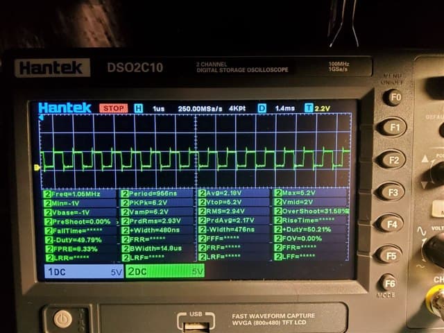
I Programmed CKOUT Fuse of Attiny84 to set(PCINT10/INT0/OC0A/CKOUT) PB2 pin as frequency generator with 1Mhz.
I have a good square 1MHz signal at the CLKIN ADC input.
I attached a photo from the oscilloscope in reply due to forum restriction
Recommended Operating Conditions from datasheet
fCLKIN External clock frequency
+----------------------+------------------+-------------------+-------------------+
| Mode | Minimum (MHz) | Nominal (MHz) | Maximum (MHz) |
+----------------------+------------------+-------------------+-------------------+
| High-resolution mode | 0.3 | 8.192 | 8.4 |
+----------------------+------------------+-------------------+-------------------+
Results in SerialPort with CS of ADC to GND: //some random values

Unfortunately, I only have a 2-channel oscilloscope. Therefore, I will send different pictures of MOSI (CH2) + CSK (CH1) and video of MISO (CH2) + CSK (CH1) measurements.
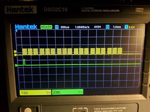
Signal on the MOSI leg of the microcontroller.
I send a 24 bit word command to read register 0x00 (A0 0000) once per second

video with SCLK + MISO Measurements
As I mentioned above, once a second I send a read command in a 24 bit word (0xA0 0000), and after this word I send 4 more words with zeros to complete a 5 word frame, +1 word during which I expect to get a response. However, each time I get different data from ADC, even though the command is the same from time to time.
Please help me figure this out, I don't know what I'm doing wrong anymore.
I'd appreciate any help
Regards, Ihor Shybka