Hello !
I received my new AD5235 ! So I tested them and it works pretty well with the help of the code you gave me (in the quote below) sherzaad.
It seems the problem I had come from the fact the board were the previous one were installed is supplied in 3.3V.
In the test I did with the new one, I can change the value of the wipers only when supplied with 5V... If it's 3.3V, they just start and take the default value, but can't take the SPI data's.
sherzaad:
/*
In order for this to work proper don't forget to add 2.2kOhm pull up resistors on READY and SDO pins
Connections
CLK - CLK
SDI - MOSI
SDO - MISO
CS - Pin 10
RDY - Pin 9
for demo purposes, have the AD5235 A1 and A2 tied to Vcc, B1 and B2 to GND
with this arrangement, you should be able to monitor W1 and W2 voltage output as the pot resistance changes
*/
//EEMEM No.--Address--EEMEM Content for …
//1 0000 RDAC1
//2 0001 RDAC2
//3 0010 USER1
//4 0011 USER2
//… … …
//15 1110 USER13
//16 1111 RAB1 tolerance
//Control Registers
#define CMD__NOTHING B00000000 //0 - Do nothing
#define CMD_MEM2RDAC B00010000 //1 - Restore EEMEM (A0) contents to RDAC (A0) register. See Table 16.
#define CMD_RDAC2MEM B00100000 //2 - Store wiper setting. Store RDAC (A0) setting to EEMEM (A0). See Table 15. - Use a delay of 50ms!!!
#define CMD_USER2MEM B00110000 //3 - Store contents of Serial Register Data Byte 0 and Serial Register Data Bytes 1 (total 16 bits) to EEMEM (ADDR). See Table 18.- Use a delay of 50ms!!!
#define CMD_DECRE6DB B01000000 //4 - Decrement by 6 dB. Right-shift contents of RDAC (A0) register, stop at all 0s.
#define CMD_DEALL6DB B01010000 //5 - Decrement all by 6 dB. Right-shift contents of all RDAC registers, stop at all 0s.
#define CMD_DECR1STP B01100000 //6 - Decrement contents of RDAC (A0) by 1, stop at all 0s.
#define CMD_DECA1STP B01110000 //7 - Decrement contents of all RDAC registers by 1, stop at all 0s.
#define CMD_ALL2RDAC B10000000 //8 - Reset. Refresh all RDACs with their corresponding EEMEM previously stored values. - Use a delay of 30us!!!
#define CMD_GETEMEM B10010000 //9 - Read contents of EEMEM (ADDR) from SDO output in the next frame. See Table 19. - Use a delay of 30us!!!
#define CMD_GET_RDAC B10100000 //10 - Read RDAC wiper setting from SDO output in the next frame. See Table 20. - Use a delay of 30us!!!
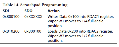
#define CMD_SET_RDAC B10110000 //11 - Write contents of Serial Register Data Byte 0 and Serial Register Data Byte 1 (total 10 bits) to RDAC (A0). See Table 14.
#define CMD_INCRE6DB B11000000 //12 - Increment by 6 dB: Left-shift contents of RDAC (A0),stop at all 1s. See Table 17.
#define CMD_INALL6DB B11010000 //13 - Increment all by 6 dB. Left-shift contents of all RDAC registers, stop at all 1s.
#define CMD_INCR1STP B11100000 //14 - Increment contents of RDAC (A0) by 1, stop at all 1s. See Table 15.
#define CMD_IALL1STP B11000000 //15 - Increment contents of all RDAC registers by 1, stop at all 1s.
#define CS 10
#define RDY 9
#include"SPI.h"
uint8_t myVal = 0;
void setup()
{
Serial.begin(9600);
//Setup SPI and start it
pinMode(CS, OUTPUT);
digitalWrite(CS, HIGH);
pinMode(RDY, INPUT_PULLUP); //that way you don't need use a external pullup resistor on this pin
SPI.begin();
delay(15);
setWiper(0, 999);
setWiper(1, 333);
Serial.print("W1 Value : "); Serial.println(getWiper(0));
Serial.print("W2 Value : "); Serial.println(getWiper(1));
stepUpOne(0);
stepUpOne(1);
Serial.print("Increase W0 with 1 : "); Serial.println(getWiper(0));
Serial.print("Increase W1 with 1 : "); Serial.println(getWiper(1));
stepUpOne(0);
repeatCMD();
stepUpOne(1);
repeatCMD();
Serial.print("W1 after repeat : "); Serial.println(getWiper(0));
Serial.print("W2 after repeat : "); Serial.println(getWiper(1));
stepDownSix(0);
stepDownSix(1);
Serial.print("Decrease W0 with 6dB : "); Serial.println(getWiper(0));
Serial.print("Decrease W1 with 6dB : "); Serial.println(getWiper(1));
stepDownSix(0);
repeatCMD();
stepDownSix(1);
repeatCMD();
Serial.print("W1 after repeat -6dB: "); Serial.println(getWiper(0));
Serial.print("W2 after repeat -6dB: "); Serial.println(getWiper(1));
SPI.end();
}
void loop()
{
}
void setWiper(uint8_t w, uint16_t value)
{
digitalWrite(CS, LOW);
myVal = SPI.transfer(CMD_SET_RDAC + w);
myVal = SPI.transfer(value >> 8);
myVal = SPI.transfer(value & 0xFF);
digitalWrite(CS, HIGH);
}
uint16_t getWiper(uint8_t w)
{
uint16_t ret;
digitalWrite(CS, LOW);
myVal = SPI.transfer(CMD_GET_RDAC + w);
myVal = SPI.transfer(CMD__NOTHING);
myVal = SPI.transfer(CMD__NOTHING);
digitalWrite(CS, HIGH);
delayMicroseconds(30);
digitalWrite(CS, LOW);
myVal = SPI.transfer(CMD__NOTHING); //Discard first byte
ret = (SPI.transfer(CMD__NOTHING) << 8);
ret += SPI.transfer(CMD__NOTHING);
digitalWrite(CS, HIGH);
return ret;
}
void stepUpOne(uint8_t w)
{
digitalWrite(CS, LOW);
myVal = SPI.transfer(CMD_INCR1STP + w);
myVal = SPI.transfer(CMD__NOTHING);
myVal = SPI.transfer(CMD__NOTHING);
digitalWrite(CS, HIGH);
}
void stepDownSix(uint8_t w)
{
digitalWrite(CS, LOW);
myVal = SPI.transfer(CMD_DECRE6DB + w);
myVal = SPI.transfer(CMD__NOTHING);
myVal = SPI.transfer(CMD__NOTHING);
digitalWrite(CS, HIGH);
}
void repeatCMD()//See page 21 in manual Another subtle feature of the AD5235 is that a subsequent CS strobe, without clock and data, repeats a previous command
{
digitalWrite(CS, LOW);
digitalWrite(CS, HIGH);
}