Starting out with the MEGA 2560

Sorry, not drawn it up yet...

Its a very basic circuit, hence reason not drawn it up, its basically the same from the other day.

Except the one one board is usb powered the other 5v powered from a 9v battery.

So will link the grounds together tomorrow and try again.

I don't like the sound of that at all from the point of view of the current capacity of the battery if it is a PP3 type as illustrated in post #148

It is but not directly powered...

9v battery powers this module to provide 5v & 3.3v

Using a PP3 to power the breadboard power supply makes things worse if anything

Can you measure 5V there?

What are these 2 wires for?

I'm not really an electronics engineer but looking at the voltage divider, can it be that the impedance of your circuit is too high?

Oh...

So how can i power things

Those two wires went off to a 10k pot, removed after photo was taken as was checking pin spacing

Oh - didnt spot that earlier

Thanks

A 5V 'phone charger would be a good start

Ok, just thought the 9v would have less noise produced

I can usb power the second board from a phone charger, i got a spare one lying about, so just use common the ground ground?

A battery will have less noise (none) but if it can't supply the required current at the required voltage then noise is not going to make any difference

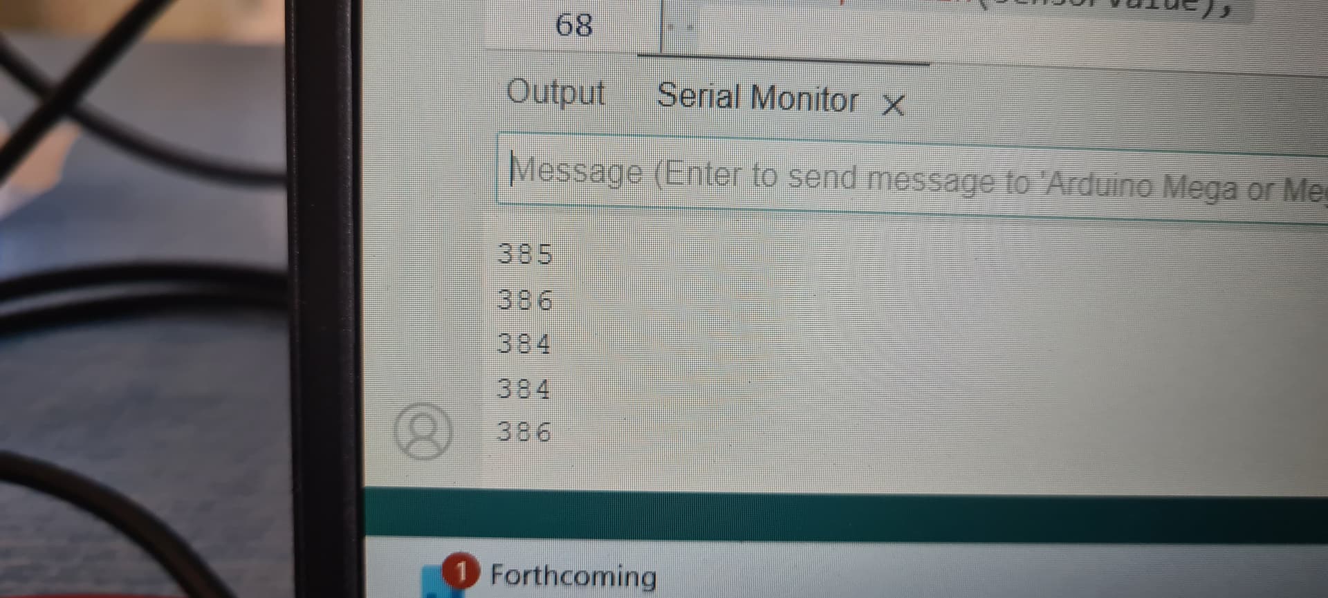
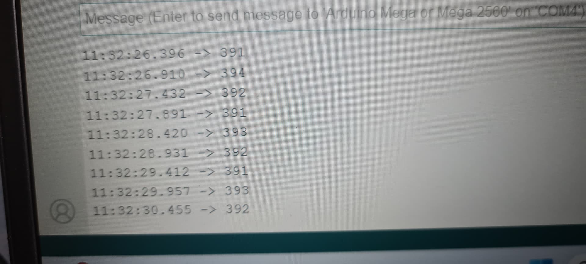
whilst i resolve the issue and find the correct USB lead to power the unit, linked the ground out from one board to the other and resolved the issue - the LCD and Serial Monitor are now displaying the same reading 374 - with 1.154vdc on the input pin A0 but the display is saying 1.83vdc (5/1023x374)

Ok rooky error not common ground between units. So more stable


Great. Now change back to lcd.print(T); to display the temp

  lcd.print("Temp = ");
  // lcd.print(T);  
  lcd.print(Vo);   // Changed to display input on Analogue Input Pin A0
  Serial.println(sensorValue);


So we got something wrong as we have a negative value -31.98 with Serial Monitor saying 392...

But some progress is better than no progress.

So this must be a maths issue now

Where did you get the formula?

  T = (1.0 / (c1 + c2*logR2 + c3*logR2*logR2*logR2));

FOUND IT

Your coefficients need to come from the table on page 4


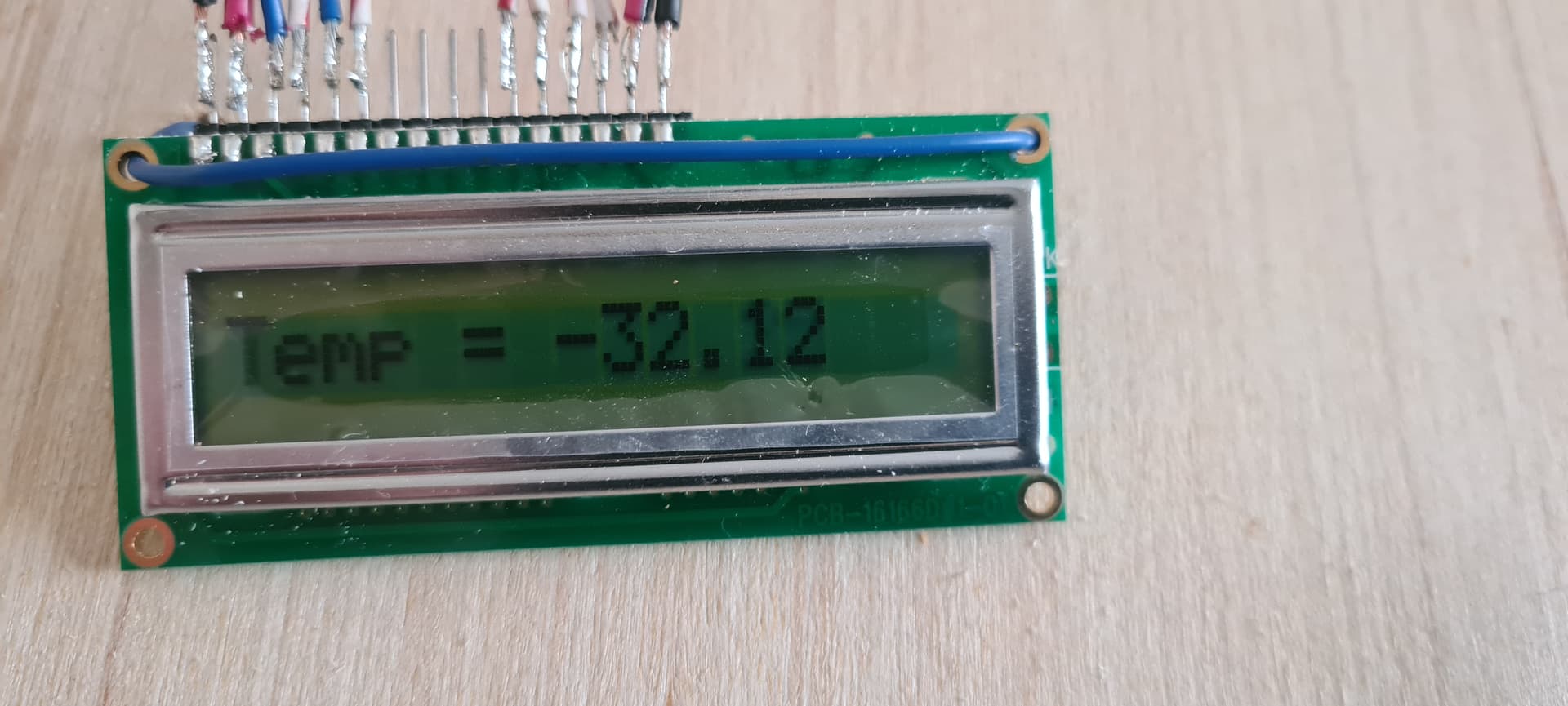
OK well i cocked that up, now got a negative value -311.70

/*
 16x1 LCD display using hd44780.h (Hitachi HD44780 driver). 

 The circuit:
 * LCD RS pin to digital pin 12
 * LCD Enable pin to digital pin 11
 * LCD R/W pin to ground
 * LCD D4 pin to digital pin 5
 * LCD D5 pin to digital pin 4
 * LCD D6 pin to digital pin 3
 * LCD D7 pin to digital pin 2
 * GND to LCD VO pin (pin 3)
*/


// include the library code:
#include <hd44780.h>
#include <hd44780ioClass/hd44780_pinIO.h> // Arduino pin i/o class header

// Sets the pins to be used by the LCD
const int rs = 12, en = 11, d4 = 5, d5 = 4, d6 = 3, d7 = 2;

hd44780_pinIO lcd(rs, en, d4, d5, d6, d7);

const int LCD_COLS = 8; // this must be left at 8 for the 16x1 LCD being used.
const int LCD_ROWS = 2;

int sensorPin = A0;    // select the input pin for the potentiometer
int sensorValue = 0;  // variable to store the value coming from the sensor

// Thermistor Setup
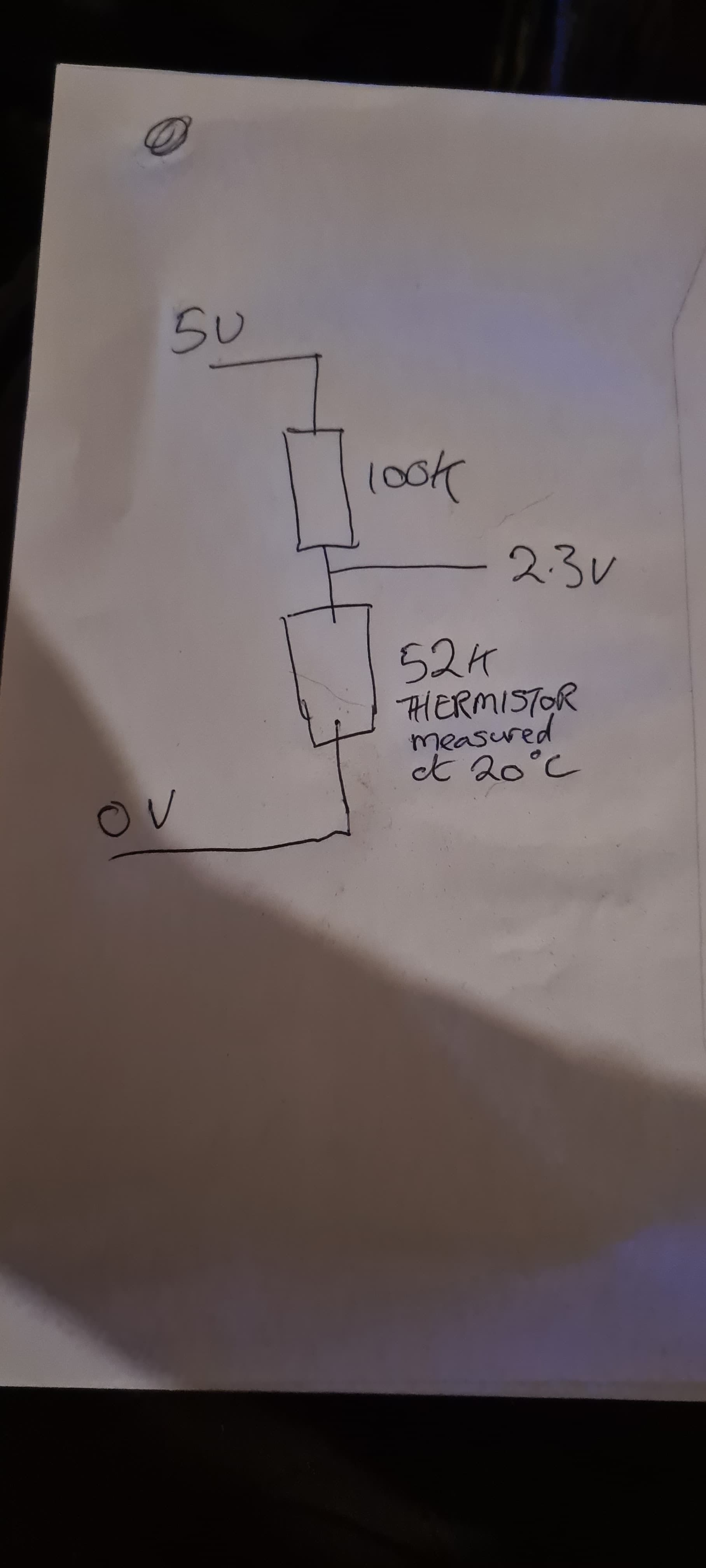
int ThermistorPin = 0; // Changed to A0 from A8
int Vo;
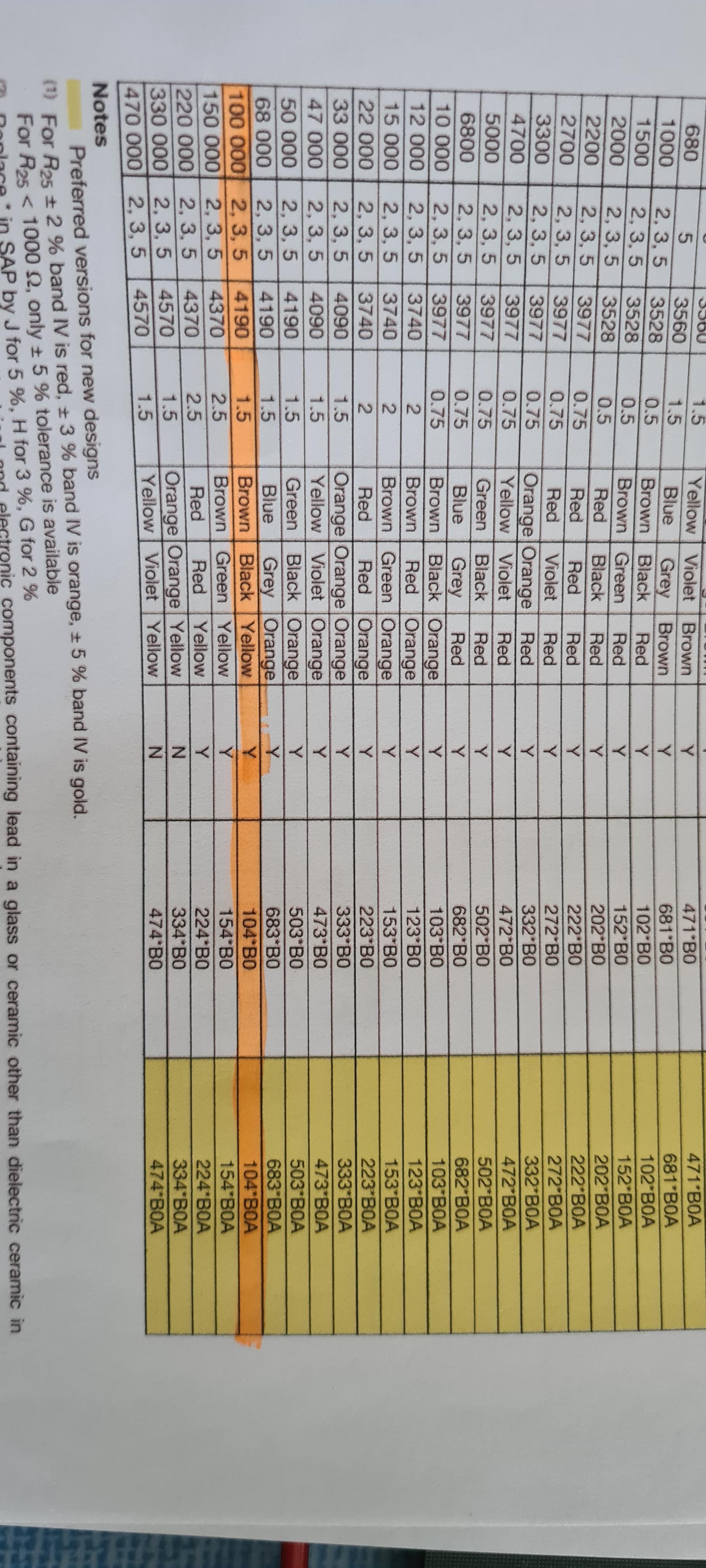
float R1 = 100000; // changed to 100K
float logR2, R2, T;
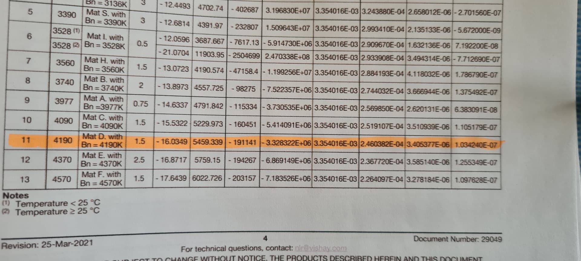
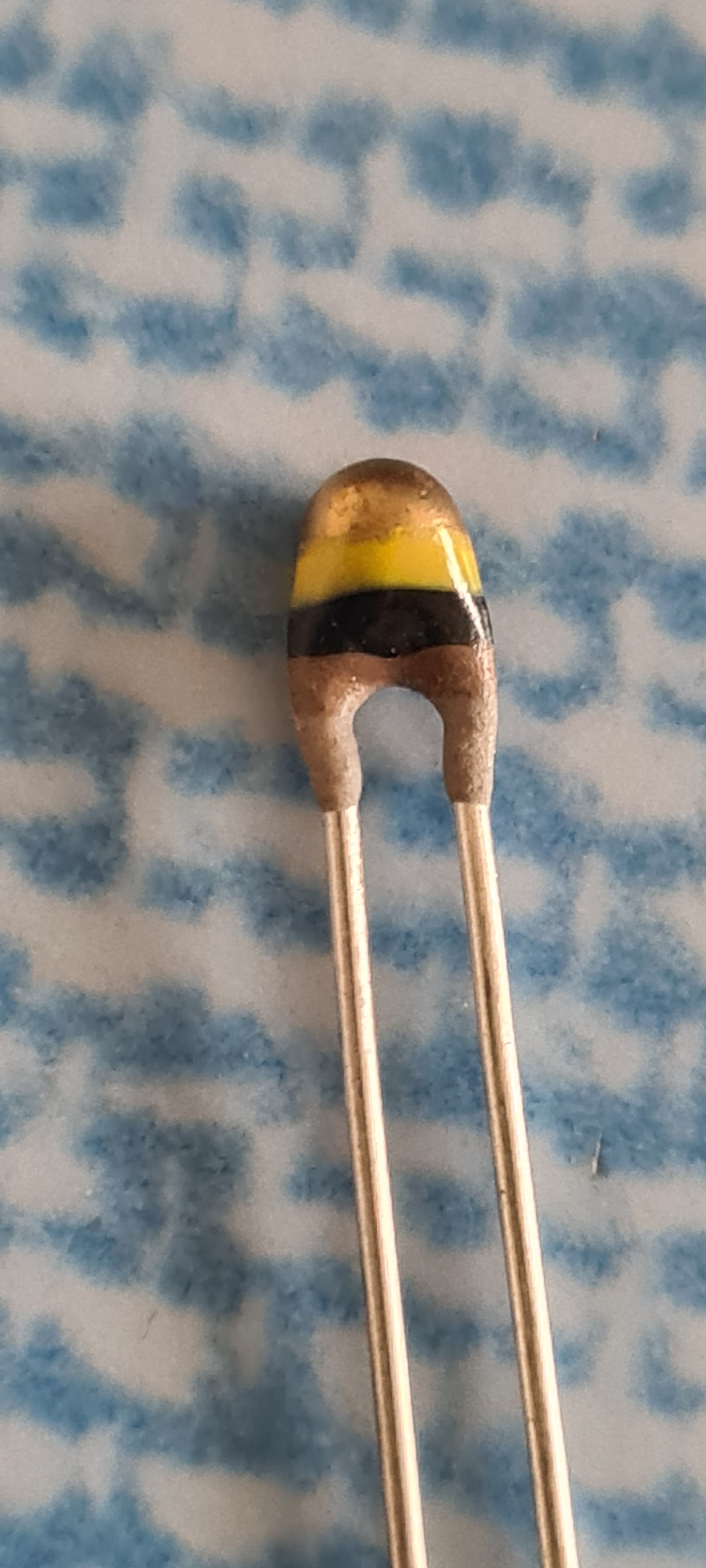
float c1 = 3.354016e-03, c2 = 2.460382e-04, c3 = 3.405377e-06; // 100K NTCLE100E3 Vishay Thermistor A1, B1 & C1 values

void setup()
{
	lcd.begin(LCD_COLS, LCD_ROWS);  // initialize LCD with number of columns and rows: 
  Serial.begin(9600);   // initialize the serial communications
 // noLineWrap() can be used to disable automatic line wrapping.
  lcd.lineWrap(); // turn on automatic line wrapping
// Print a message to the LCD
	lcd.print("Let Us Begin!");
  delay(2000); // 2 second delay

}

void loop() 
{ 
    lcd.clear(); // Clear Screen of existing data
  
  Vo = analogRead(ThermistorPin); // Thermistor Settings
    
  sensorValue = analogRead(sensorPin); // read the value from the sensor:

  R2 = R1 * (1023.0 / (float)Vo - 1.0); // 100k x (1023/ 392 -1.0) = 160,969.3878
  logR2 = log(R2);
  T = (1.0 / (c1 + c2*logR2 + c3*logR2*logR2*logR2));
  T = T - 273.15; // Temp in Kelvin
  T = (T * 9.0)/ 5.0 + 32.0; 

  lcd.print("Temp = ");
  lcd.print(T);  
  // lcd.print(Vo);   // Changed to display input on Analogue Input Pin A0
  Serial.println(sensorValue);
  
  delay(500);  
  lcd.clear(); // Clear Screen of existing data           
  }
  

Try K-1(B1) K-2(C1) K-3(D1) values. I'm grasping now

Try this code. It prints in the serial monitor, not the LCD

//Thermometer with thermistor

/*thermistor parameters:
 * RT0:  100 000 Ω
 * B: 4190 K +- 0.75%
 * T0:  25 C
 * +- 5%
 */

//These  values are in the datasheet
#define RT0 100000   // Ω
#define B 4190     //  K
//--------------------------------------


#define VCC 5    //Supply  voltage
#define R 100000  //R=100KΩ

//Variables
float RT, VR, ln, TX,  T0, VRT;

void setup() {
  Serial.begin(9600);
  T0 = 25 + 273.15;                 //Temperature  T0 from datasheet, conversion from Celsius to kelvin
}

void loop() {
  VRT = analogRead(A0);              //Acquisition analog value of VRT
  VRT  = (5.00 / 1023.00) * VRT;      //Conversion to voltage
  VR = VCC - VRT;
  RT = VRT / (VR / R);               //Resistance of RT

  ln = log(RT / RT0);
  TX = (1 / ((ln / B) + (1 / T0))); //Temperature from thermistor

  TX =  TX - 273.15;                 //Conversion to Celsius

  Serial.print("Temperature:");
  Serial.print("\	");
  Serial.print(TX);
  Serial.print("C\	\	");
  Serial.print(TX + 273.15);        //Conversion to Kelvin
  Serial.print("K\	\	");
  Serial.print((TX * 1.8) + 32);    //Conversion to Fahrenheit
  Serial.println("F");
  delay(500);

}