And another update

Just to understand, where do you take the data of how much do you have to move the camera to follow the stars?
aster94:
Just to understand, where do you take the data of how much do you have to move the camera to follow the stars?
You mean the calculation of how much the motor must rotate to counteract the movement of the stars?
Here is the arduino code for the startracker
I have the right gears, so its just a matter of connecting the boards, wires and motor right..
If you use a non-permanent magnet type stepper, and you only step it
periodically, you can shut the power of to the stepper when not stepping.
You do have to wait for the step to complete ( remember that armature is
moving in the stepper ).
This can significantly reduce power.
Dwight
I've now builded the startracker using arduino UNO, A4988 and NEMA 17 motor.
I removed the LCD screen since I don't really need it. And it saves a lot of power.
I've connected everything, and added the code. I can hear that the motor has power and is on. But when I press start, nothing happens.
What is wrong?
#define  BACK_PIN  13
#define  STOP_PIN  12
#define  START_PIN 11
#define  ENABLE_PIN 6
#define  DIR_PIN 5
#define  LED_ON_PIN 10
#define  LED_OFF_PIN 9
#define  LED_BACK_PIN 8


#define COMINGUPSPEED 1.25
#define LENGTH 228
// Calculus here:
#define STEP ((2*3.14159)/1436)*LENGTH //rotational velocity of the small gear

#define RPS (STEP/(60*0.2549))/COMINGUPSPEED //rotational velocity of the large gear

#define ZERO_SPEED 65535
#define STEPS_PER_REV 3200     // 200 steps motor with 1/16 microstepping
#define MAX_RPM (RPS*60.0)

// BIT functions
#define CLR(x,y) (x&=(~(1<<y)))
#define SET(x,y) (x|=(1<<y))

//uint16_t rpm;
float rpm;
uint16_t period;
uint16_t userCommand=0;
uint8_t motor_enable;

// TIMER 1: STEP INTERRUPT
ISR(TIMER1_COMPA_vect)
{
  if (motor_enable)
    {
    SET(PORTB,4);
    delayMicroseconds(2);
    CLR(PORTB,4);
    }
}

void setRpm()
{
  float temp;
  if (rpm == 0)
  {
    ICR1 = ZERO_SPEED;
    digitalWrite(ENABLE_PIN,HIGH);  // Disable motor
  }
  else
  {
    digitalWrite(ENABLE_PIN,LOW);  // Enable motor
/*   if (rpm<8)
      rpm = 8;*/
    if (rpm>MAX_RPM)
      rpm = MAX_RPM;
    temp = (rpm/60.0)*STEPS_PER_REV;
    temp = 2000000 / temp;          //  2000000 = (16000000/8) timer1 16Mhz with 1/8 preescaler
    if (period<600000)
      period=60000;
    period = temp;
    while (TCNT1 < 30);   // Wait until a pulse to motor has finished
    //cli();
    ICR1 = period; //+ userCommand;
    if (TCNT1 > ICR1)     // Handle when we need to reset the timer
      TCNT1=0;
    //sei();
  }
}

int buttonSTARTState = 0;
int buttonSTOPState = 0;
int buttonBACKState = 0;
int ENABLEState = 1;
int DIRState = 0;
int LED_ON_State = 0;
int LED_OFF_State = 0;
int LED_BACK_State = 0;

void setup() {

  // Set up the three button inputs, with pullups
  pinMode(BACK_PIN, INPUT_PULLUP);
  pinMode(STOP_PIN, INPUT_PULLUP);
  pinMode(START_PIN, INPUT_PULLUP);
  pinMode(ENABLE_PIN, OUTPUT);
  pinMode(DIR_PIN, OUTPUT);
  pinMode(LED_ON_PIN, OUTPUT);
  pinMode(LED_OFF_PIN, OUTPUT);
  pinMode(LED_BACK_PIN, OUTPUT);

  Serial.begin(115200);
  digitalWrite(LED_OFF_PIN, HIGH);
  motor_enable = 0;
    // PWM SETUP
  // Fast PWM mode => TOP:ICR1
  TCCR1A =(1<<WGM11);
//  TCCR1B = (1<<WGM13)|(1<<WGM12)|(1<<CS10);   //No Prescaler, Fast PWM
   TCCR1B = (1<<WGM13)|(1<<WGM12)|(1<<CS11);   // Prescaler 1:8, Fast PWM
  ICR1 = ZERO_SPEED;
  TIMSK1 = (1<<OCIE1A);  // Enable Timer interrupt

  rpm = 0;

  while (digitalRead(START_PIN)==HIGH);    // Wait until START button is pressed
  motor_enable = 1;
  digitalWrite(LED_OFF_PIN, LOW);
  digitalWrite(LED_ON_PIN, HIGH);
  delay(250);
  while (digitalRead(START_PIN)==LOW);
}

void loop() {

  buttonSTARTState = digitalRead(START_PIN);
  buttonSTOPState = digitalRead(STOP_PIN);
  buttonBACKState = digitalRead(BACK_PIN);
  ENABLEState = digitalRead(ENABLE_PIN);
  DIRState = digitalRead(DIR_PIN);
  LED_ON_State = digitalRead(LED_ON_PIN);
  LED_OFF_State = digitalRead(LED_OFF_PIN);
  LED_BACK_State = digitalRead(LED_BACK_PIN);

if (digitalRead(START_PIN)==LOW)   // START/STOP Button pressed?
    {
    rpm = 0;
    userCommand=0;
    setRpm();
    if (motor_enable == 1)
      motor_enable = 0;
    else
      motor_enable = 1;
    while (digitalRead(START_PIN)==LOW);   // Wait until botton release
    }
    if (digitalRead(BACK_PIN)==LOW)   //  Button BACK pressed?
    {
         digitalWrite(DIR_PIN,HIGH);    // Motor direction

          rpm=50;
        setRpm();

        if (motor_enable == 1)
          motor_enable = 0;
        else
          motor_enable = 1;

    while (digitalRead(BACK_PIN)==LOW);   // Wait until botton release
    }
     if (motor_enable)
      {
        rpm++;
        digitalWrite(LED_ON_PIN,HIGH);
      }
      else
      {
        rpm = 0;
        digitalWrite(LED_ON_PIN,LOW);
      }

if (digitalRead(STOP_PIN)==LOW)   // Decrease button
    {
    digitalWrite(LED_ON_PIN,LOW);
    userCommand--;
    while (digitalRead(STOP_PIN)==LOW);  // Wait until released
    }
  if (digitalRead(BACK_PIN)==LOW)   // Increase button
    {
    digitalWrite(LED_ON_PIN,LOW);
    userCommand++;
    while (digitalRead(BACK_PIN)==LOW);  // Wait until released
    }
}
Hi,
Have you got the wires from the stepper phased properly,
You have 4 wires coming out of the stepper, they are two wires for each of the two separate windings.
Swap one pair around, see if that helps.
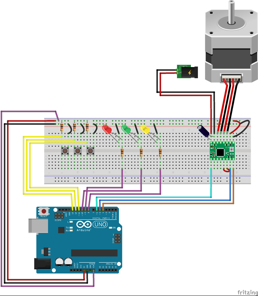
Can you please post a copy of your circuit, in CAD or a picture of a hand drawn circuit in jpg, png?
Tom..... ![]()
Hi,
If your stepper setup is like this.

Swap A1 and B1 to change the phasing of the windings.
Tom... ![]()
TomGeorge:
Hi,
If your stepper setup is like this.
Swap A1 and B1 to change the phasing of the windings.Tom...

Yes, I follow that exact drawing. The only difference is that I use a 47uf condensator.
And I found out what wires belongs to what coil on the motor.
You think its just a +- problem?
The code looks correct, you think?
I have tested the setup with another simpler code that just runs the motor, and that works fine. But I need this code to work because of the specific rpm it needs to run at.
Hi,
If the driver and stepper combination works with a simpler code, then I'd say the setup is fine.
I'm just heading to bed, just on 11:25pm here,
If I get a chance tomorrow, I'll have a look.
Someone here during my nighttime may have the solution.
Tom... ![]()
As long as there is a pulse on the coils, they will move. The polarity
is only the direction of movement.
I saw one thing in the setup() that may be an issue.
    if (period<600000)
      period=60000;
    period = temp;
Why do you set period and then overwrite it right away.
Also, did you intend to have <600,000 to 60,000? Maybe
to many 0s?
You have stated that it didn't run, you didn't say if the LEDs
responded to the buttons?
Dwight
dwightthinker:
As long as there is a pulse on the coils, they will move. The polarity
is only the direction of movement.
I saw one thing in the setup() that may be an issue.if (period<600000)
period=60000;
period = temp;
Why do you set period and then overwrite it right away. Also, did you intend to have <600,000 to 60,000? Maybe to many 0s? You have stated that it didn't run, you didn't say if the LEDs responded to the buttons? Dwight
The main code is written by JJRobots. I don't have enough experience in arduino coding to write it myself. I only added the LED's and tried to change the code to my setup. The only led that works is the OFF light. When I press any buttons the OFF light goes of and nothing else happens.
Here's the original code:
You have resistors for all the switches. This isn't needed
if using the internal pullups.
Why do you have +5V and VIN connected together?
Have you checked that all of the power connections,
- and ground are actually connect to where you think they
are.
Use an LED and resistor for a simple test probe.
Dwight
Oki, and update. I checked and rechecked everything. Found out that the leds was connected wrong. Now they all work. But still no go on the motor. I can hear that the motor humz when power is connected and makes a clunk noise when I press the buttons. But it still wont move.
I tried to change the pins for the motor, but same result. It humz when power is connected and makes clunky noises when I the buttons.

Hi,
If you are using that type of tactile press button, check that you have them oriented the correct way so that you are connected to the correct switch terminals.
Tom... ![]()
TomGeorge:
Hi,If you are using that type of tactile press button, check that you have them oriented the correct way so that you are connected to the correct switch terminals.
Tom...
I belive they are, because they are turning the leds on and off.
What about the VIN wire?
Dwight
You need to connect both grounds together. Both the ones from the stepper
supply and the arduino ground.
Dwight
dwightthinker:
What about the VIN wire?
Dwight
The VIN wire was just from a tutorial, I tried to use a potentiometer to control the motor. But found out that its better to have the 3 buttons to controll direction instead. Just forgot to remove the VIN wire.
dwightthinker:
You need to connect both grounds together. Both the ones from the stepper
supply and the arduino ground.
Dwight
They are connected. Aren't they?