Hello everyone, this is my first post here, and it concerns my first Arduino project which I've been working on for a couple of weeks. I have tried to follow the forum guidelines on code etc, but please bear with me if I don't get the formatting right first time. Also, apologies if this post is a bit long-winded; I just want to give as much relevant information as possible. A bit of background:
I am fairly comfortable with the mechanical side of things, and figuring out wiring and prototyping the hardware. I have to admit I am struggling with the coding, and have probably relied too much on AI rather than sticking at learning the coding better.
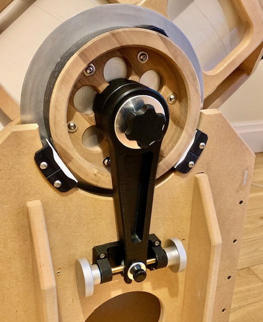
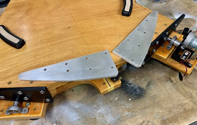
I have recently built a DIY Dobsonian telescope mount (basic altitude and azimuth). Altitude is swinging the 'scope up and down vertically, azimuth is rotating the whole thing on its base such that it can be manually pointed at any target in the sky. I also built a DIY equatorial platform, which couteracts the Earth's rotation so that images in the eyepiece don't slowly drift out of sight. This can be particularly annoying at high magnifications, when a target can move across the field of view in minutes (or less) if it's not compensated for. The equatorial platform is currently powered by a small off-the-shelf 9V DC motor/gearbox, and works very well in terms of freezing a target object. This is the setup pretty much as it is now:

This is all great, but trying to manually nudge the 'scope to center a star or planet at high magnification in the eyepiece is literally hit-and-miss, especially with the inherent stick/slip of the bearings - and it gets frustrating. I thought if I could power the altitude & azimuth axes with stepper motors, and be able to step them in tiny increments with encoders, this would be great; I'd be able to leave the tracking motor running and fine-tune the position of the image in the eyepiece, then, when set it would stay there. I did some calculations and all seemed well in terms of gearing and steps/microsteps etc.
I obtained some NEMA17 stepper motors (17HS13-0404S), and an Elegoo UNO R3 starter pack, and got started. A colleague at work suggested Adafruit's TMC2209 Stepper Motor Driver Breakout Boards, and Adafruit I2C QT Rotary Encoder Breakouts would be suitable. I'm using a 12V 2A plug-in power supply, in conjunction with a 330 microfarad, 16V capacitor. Another colleague lent me his "Arduino for Dummies" book. I got to work wiring everything up, and got AI to write me some code. Eventually I got the two steppers working nicely with the encoders. I have built a leadscrew mechanism to drive the altitude axis, and am working on the azimuth mechanism.
I then thought why not also replace the 9V battery powered equatorial drive motor with another stepper - I could after all then just use one battery for all motors, and the stepper would hopefully be more consistent. I then prototyped a simple variable speed drive using a 10 K Ohm potentiometer. Again I got AI to write the code, and after a bit of fiddling around got it working well, the speed varying as it should. However...when I come to combining the two sets of code - position and speed - into one (again using AI), the speed control doesn't work properly. Rather than varying from zero (or a minimum) to the maximum, it only runs at one speed. Or at least any variation in speed is imperceptible. When run in isolation with its own code, the speed range on that motor is obvious when adjusted with the potentiometer. The actual speed I'll need for this drive is very low - about 0.09 r.p.m. (in case that's relevant to the discussion).
I have tried removing the encoder bits of code completely, and then the motor speed control works as it should. It has been suggested by my collegue that the issue may be with how the program is being read and the processing speed of the Arduino. I have fiddled with "Delay" times, but to no avail.
Here is the combined code (I can post the individual codes that both work if necessary):
#include <Wire.h>
#include <Adafruit_seesaw.h>
#include <AccelStepper.h>

// Create seesaw objects for two encoders
Adafruit_seesaw encoder1;
Adafruit_seesaw encoder2;

// Define TMC2209 pins for Motor 1 (Encoder-controlled)
#define DIR_PIN1 2
#define STEP_PIN1 3
#define ENABLE_PIN1 5

// Define TMC2209 pins for Motor 2 (Encoder-controlled)
#define DIR_PIN2 6
#define STEP_PIN2 7
#define ENABLE_PIN2 8

// Define pins for Motor 3 (Potentiometer-controlled with AccelStepper)
#define DIR_PIN3 10
#define STEP_PIN3 11
#define POT_PIN A0

// Define scaling factor for encoder to motor steps
const int stepsPerEncoderStep1 = 4;
const int stepsPerEncoderStep2 = 4;

int16_t lastEncoderPosition1 = 0;
int16_t lastEncoderPosition2 = 0;

// Create AccelStepper object for Motor 3
AccelStepper stepper(AccelStepper::DRIVER, STEP_PIN3, DIR_PIN3);

void setup() {
  // Initialize serial for debugging
  Serial.begin(115200);

  // Initialize I2C for Encoder 1
  if (!encoder1.begin(0x36)) {
    Serial.println("Encoder 1 not found!");
    while (1);
  }

  // Initialize I2C for Encoder 2
  if (!encoder2.begin(0x37)) { // Assuming encoder 2 is on address 0x37
    Serial.println("Encoder 2 not found!");
    while (1);
  }

  // Initialize TMC2209 pins for Motor 1
  pinMode(DIR_PIN1, OUTPUT);
  pinMode(STEP_PIN1, OUTPUT);
  pinMode(ENABLE_PIN1, OUTPUT);
  digitalWrite(ENABLE_PIN1, LOW);

  // Initialize TMC2209 pins for Motor 2
  pinMode(DIR_PIN2, OUTPUT);
  pinMode(STEP_PIN2, OUTPUT);
  pinMode(ENABLE_PIN2, OUTPUT);
  digitalWrite(ENABLE_PIN2, LOW);

  // Initialize TMC2209 pins for Motor 3
  pinMode(DIR_PIN3, OUTPUT);

  // Set up AccelStepper for Motor 3
  stepper.setMaxSpeed(8000); // Steps per second
  stepper.setAcceleration(500); // Steps per second^2
  digitalWrite(DIR_PIN3, HIGH); // Set direction to forward

  // Start at position 0 for both encoders
  lastEncoderPosition1 = encoder1.getEncoderPosition();
  lastEncoderPosition2 = encoder2.getEncoderPosition();
}

void loop() {
  // Handle Encoder 1 and Motor 1
  int16_t encoderPosition1 = encoder1.getEncoderPosition();
  int stepsToMove1 = (encoderPosition1 - lastEncoderPosition1) * stepsPerEncoderStep1;
  if (stepsToMove1 != 0) {
    digitalWrite(DIR_PIN1, stepsToMove1 > 0 ? HIGH : LOW);
    for (int i = 0; i < abs(stepsToMove1); i++) {
      digitalWrite(STEP_PIN1, HIGH);
      delayMicroseconds(100000);
      digitalWrite(STEP_PIN1, LOW);
      delayMicroseconds(100000);
    }
    lastEncoderPosition1 = encoderPosition1;
  }

  // Handle Encoder 2 and Motor 2
  int16_t encoderPosition2 = encoder2.getEncoderPosition();
  int stepsToMove2 = (encoderPosition2 - lastEncoderPosition2) * stepsPerEncoderStep2;
  if (stepsToMove2 != 0) {
    digitalWrite(DIR_PIN2, stepsToMove2 > 0 ? HIGH : LOW);
    for (int i = 0; i < abs(stepsToMove2); i++) {
      digitalWrite(STEP_PIN2, HIGH);
      delayMicroseconds(100000);
      digitalWrite(STEP_PIN2, LOW);
      delayMicroseconds(100000);
    }
    lastEncoderPosition2 = encoderPosition2;
  }

  // Debugging information for encoders
  Serial.print("Encoder 1 Position: ");
  Serial.println(encoderPosition1);
  Serial.print("Steps for Motor 1: ");
  Serial.println(stepsToMove1);
  Serial.print("Encoder 2 Position: ");
  Serial.println(encoderPosition2);
  Serial.print("Steps for Motor 2: ");
  Serial.println(stepsToMove2);

  // Handle Potentiometer and Motor 3
  int potValue = analogRead(POT_PIN);
  float motorSpeed = map(potValue, 0, 1023, 0, 8000);
  stepper.setSpeed(motorSpeed);
  stepper.runSpeed();
}
Here is the circuit diagram (apologies if it's unclear, any suggestions for improving it gratefully accepted):

Any suggestions on how to get this code working as one would be really appreciated.
Another question is regarding back-driving the azimuth motor: As I mentioned, this will be a friction drive of a small pulley against a larger slew bearing (actually a re-purposed lazy susan base). I am designing the motor/pulley to be easily brought into and out of contact using an over-centre mechanism. However, if I forget to dis-engage it, or accidentally nudge the 'scope, I guess this could overcome the holding torque of the motor and back-drive it at quite a speed. Is this an issue? Should I incorporate some kind of diode system? It's not a problem with the altitude mechanism, becasue the leadscrew can't be back-driven.
Thanks very much in advance for any suggestions.