I'm trying to get the steering controls working with a chinese no-name head unit, in a 2008 peugeot 207.
This car uses CAN to send its control stalk signals to the factory head unit, so I'm guessing there is a CAN encoder within the stalk that turns the push buttons into CAN signals.
That's no problem, there's tonnes of places to find schematics for CAN sniffers. The problem I have is the interface with the new head unit.
It comes with two wires, as many chinese units do, labelled as "WC1+" and "WC2+", I've also seen "KEY1/KEY2" and "K1/K2" and many other variants on that, but it's typically a two wire interface, that isn't a CAN signal.
Looking around the web I worked out that these no-name head units tend to use a resistive input, and although I haven't actually tried learning mode on the head unit yet, I'm going to assume that's the route I'll need to take.
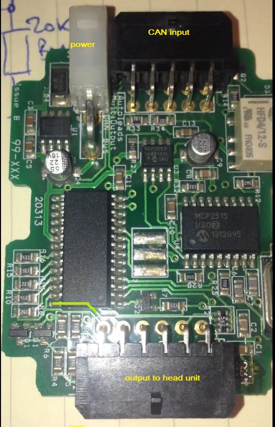
So I went and got myself an adapter which is specified for this car, Autoleads PC99-X87. It was dirt cheap, had all the wires hacked off, and no instructions, but I only really wanted to reverse engineer it so that I can see what I'm up against.
It appears that these units are widely available with a diversity of OEM connectors and head unit connectors which can be bought additionally, I'll come to that shortly.
Opening the unit up reveals the usual bundle of CAN decoder IC's which ultimately end up feeding a PIC, however the first thing I notice about the PIC is what I believe to be the jackpot for my project.
Connected to each pin of port A is an array of resistors with different values. The other side of the resistors is commoned and goes to a pin on the PCB socket which then connects out to the head unit. One pin of port A is not connected to a resistor, but goes off to another pin on the PCB socket to the head unit.
Autoleads will sell you an additional connector which plugs into the PCB socket and then has trailing leads with various ends on to suit all brands of both big name and no name head units. And sure enough, those connecting wires are located on the socket pins where the resistor array connects to.
I don't know much about PIC, it's been a long time since I used one, but it appears to me as though this one is being used as some kind of digital pot, or selectable resistor array, but how?
How does the firmware tell the IC pins to connect to eachother and not just to 1 or 0?
Anyhow, it seems this is the way forward from here, so I'd appreciate any suggestions how I could create a selectable resistor array on arduino in this same fashion? Frankly I'm tempted to use this module as it is, leaving the CAN side intact and just pulling the PIC off the board so I can tap the tracks. I've read about baud rates and PID's and all that stuff, why muck about with that when Autoleads have already done the hard work specific to my particular CAN protocol.
If I'm barking up the wrong tree put me straight, it just stands out to me how those resistor values are apparently deliberately staggered upwards in value with large gaps, seemingly to eliminate false triggering from resistors that may stray out of tolerance.
For anyone else interested in this application, here's a couple of links I found in passing that are specific to Peugeot 207 CAN, and might help you.
http://romain.raveaux.free.fr/teaching/TP207.pdf
Photo attached, cheers all.