It uses no real code because 2 square waves in quadrature from the encoder works fine to drive a STEP+DIR stepper driver:
/*

  Stepper Motor A4988 Driver Example

  No code here - use a quadrature encoder to rotate a single step

Depends on the encoder clock signal driving STEP while te DATA signal
indicates direction

 A4988:  STEP| DIR
 Encoder: CLK| DT
           0 | 0
           1 | 0
           1 | 1
           0 | 1

Built from https://wokwi.com/projects/327823888123691604


*/

void setup() {}
void loop() {}
See also this simulation using the Arduino Stepper.h library driving a STEP+DIR driver with its two-wire quadrature constructor: Stepper myStepper(stepsPerRevolution, 8, 7);
/*
 Stepper Motor Control using a stepper driver with Stepper.h - one revolution

Simulation https://wokwi.com/projects/360724869269076993

code from
 https://github.com/arduino-libraries/Stepper/blob/master/examples/stepper_oneRevolution/stepper_oneRevolution.ino
Modified to a two-wire/quadrature setup for a stepper driver

for https://forum.arduino.cc/t/questions-about-my-hx711-stepper-project/1102568/29
and https://github.com/arduino-libraries/Stepper/issues/40

 This program drives a stepper motor using a driver.
 The motor driver STEP input is attached to digital pin 8 of the Arduino.
 The motor driver DIR is attached to digitalPin 7
 The digital pin 9 is attached to a DIR status led.
 The motor should revolve one revolution in one direction, then
 one revolution in the other direction.
 Created 11 Mar. 2007
 Modified 30 Nov. 2009
 by Tom Igoe

 Modified 2023-03-31 by drf5n

 */

#include <Stepper.h>

const int stepsPerRevolution = 200*4;  // change this to fit the number of steps per revolution
// for your motor.  The *4 factor is due to the 4 steps/cycle change in the
// Stepper.h two-wire quadrature output setup
// note that the DIR pin toggles in step with the STEP pin, but
// with the level HIGH or LOW depending on direction

//This scheme works per the table at
// https://github.com/arduino-libraries/Stepper/blob/master/src/Stepper.h#L64-L72
/*  The sequence of control signals for 2 control wires is as follows
 * (columns C1 and C2 from above):
 *
 * Step C0 C1
 *    1  0  1
 *    2  1  1
 *    3  1  0
 *    4  0  0
 * If C0 = STEP, and C1 = DIR
 * and the step 2 is the leading edge of STEP, then DIR is high
 * and in the opposite direction, if 3 is the leading edge of STEP,
 * then DIR is low.
 */
// Per https://forum.arduino.cc/t/change-stepper-dir-according-to-predifined-analog-input-value/1118716/25
// and

// initialize the Stepper library on pins 8 through 11:
//Stepper myStepper(stepsPerRevolution, 8, 9, 10, 11);
// Use 1 pin as STEP and other for DIR
Stepper myStepper(stepsPerRevolution, 8, 7);
const int dirPin = 7;


void setup() {
  // set the speed at 60 rpm:
  myStepper.setSpeed(60);
  // initialize the serial port:
  Serial.begin(9600);
}

void loop() {
  // step one revolution in one direction:
  Serial.println("clockwise");
  myStepper.step(stepsPerRevolution);
  delay(500);

  // step one revolution in the other direction:
  Serial.println("counterclockwise");
  myStepper.step(-stepsPerRevolution);
  delay(500);
}
I don't really have a question. I thought it was an interesting feature of quadrature signals.
Looking at the Arduino Stepper.h library, I had thought the two-wire config was for some odd two-wire stepper motor configuration. With both pins toggling, I didn't think it would work with a STEP+DIR driver, only with the buffer-driver type drivers.
Then for that other thread, I tried to show how you could use a phase of the stepper to drive the step input and manage the direction separately. Then the OP hooked up both pins and said it worked great. I saw some high-end stepper drivers that advertise quadrature input, and realized that it works fine with STEP+DIR, if you don't mind if your DIR pin toggles in quadrature with your step signal.
Then I thought it would work just as well with an encoder with pullups & simulated that.
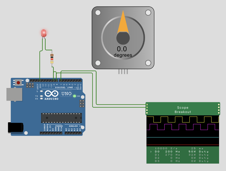
I can see how it might work, looking at your scope picture, when the step pin goes HIGH, causing the driver to step,the dir pin is always LOW, going the other direction, the dir pin is always HIGH. Don' know how max speed or acceleration would be affected though. Guess I'll dig out a stepper and see.