And nothing is attached to my arduino.except for USB of course.
is that an EM interference?i'm using a LCD and (as far as i know) triggering those values would require more than a cellphone on the desk or a nearby pc...
Can you help me or clarify why this happens?
some time i get aval=0 bval=14 (or similar values).
I tried adding and removing the Pnmode instruction, but that's not the problem (the ports 1 and 10 are inputs by default anyway!)
this happens with all the analog ports.
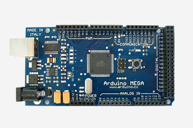
I forgot i've an arduino Mega.
Thanks in advance for any help!
with NOTHIN attached to...how can measure 1 if there is not even a wire attached?I cannot do anything,buttons or other inputs...I tried a simple switch it keeps sayin 1,1,1,1....
is my arduino gone crazy?
i tried also enabling pullup resistor but nada...still same problem.
Like Groove said, your inputs are floating, ie they are undefined, you can make them read one way or the other by using a pull up / pull down resistor. You can either use a physical resistor (10-100k is nice) between the pin and ground (pulldown) or between the pin and 5v (pullup). Or you can enable an internal resistor in software to make it go one way or the other. for example if you wanted to detect a switch being turned on digital pin 4, wire a switch between pin 4 and ground and use
pinMode(4, INPUT);
digitalWrite(4, HIGH); // internal pull up
in the setup part of the sketch.
you can then read the switch using digitalRead, it will be low when the switch is closed and high when its open.
You're connecting the switch between the pin and ground aren't you ? Using a pullup and connecting it between the pin and 5V will mean it reads high all the time.
I'm a little confused. Your last post shows reading digital inputs with their internal pull-ups enabled, so they should read 1 (HIGH) if you ground the pin it will read 0 (LOW), so your results are as expected.
Your original post was about analog inputs, and floating analog inputs will result is random valves returned if not wired to a source voltage or ground, and the internal pull-up option does not apply to analog input reads.
So what exactly are you trying to understand?
Just to be clear you know that analog input pin 0 is not the same pin as digital pin 0, right?
The arduino, like any digital device, is only capable of reading a logical '1' or a logical '0' from a digital input. It has no concept of anything else in that context, so it must choose one or the other. You may think you have nothing connected to the input, but in reallity lots of things are capacitively or inductively or resistively coupled through e.g. the circuit board substrate or the very air surrounding the chip. Those things are usually negligible and drowned out by the valid signal when you've got something deliberately connected, but if not then those other things can cause the input to drift towards one or zero depending on what's going on around it. The same goes for the analog inputs. If you touch your finger to one of the analog inputs with nothing else attached you will cause the readings to change, for example, since your body has measurable resistive and capacitive proeprties.
Think of it like a weather vane; if you have a strong steady wind you will get meaningful readings. If it's mostly calm but with gentle intermittent breeze, though, it will just drift around rather randomly. Connecting a pullup or pulldown resistor or a valid TTL signal will provide that strong steady wind.
well...
i was trying a light sensor and i noticed that i have to map values to have a correct feeback (axample: with no light was 300, full light was 500, so i did map(var,300,500,0,255); )
This was my original problem.
I'm now aware that there is a EM "noise" that should be considered.
My real concern was...it is normal than, in a scale from 0 to 1024 (AnalogRead values) having nothing connected to the designed probe pin can trigger a feedback of 300-400 or even 500?That is really a huge amount it's like sayin it is picking up almost 50% of the +5v,right?.
Also, i'm aware that any little thing can trigger a logic state 0 or 1, but despite having understood how to fix it for the analog in (with map as i said..at least this is how i do it.) i'm unable to read 0 from a connected pin or a pressed switch/button, even with pullup resistor enabled internally AND externally.
Maybe i'm wrong but the first tests i did with my arduino i did not had this problems.Pin disconnected = analogRead 0.
Right now i'm reading 1 with ANY pin grounded,and the arduino is completely free of other hardware/cables except the USB!
Forgive me if i'm misunderstanding something obvious, i'm following the learning section which is great to start but this problem is just unexpected for me,at least for what i know.
The results you are getting are perfectly normal and mean your arduino is working 100% correctly.
When you enable a "pullup" it very weakly connects the input internally to 5V, so when nothing else is connected, it reads that pin as HIGH, which is equal to digital 1.
Similarly with the analog inputs - when nothing is connected, it can read anything between 0 and 5V.
Remember that there are small voltages everywhere, for example static electricity can read in the thousands of volts, and since there is nothing to overcome those small voltages in the atmosphere, they are what the arduino reads.
Do a bit more reading/googling using the terms people here have given you - specifically "floating", and "pullup".
Right now i'm reading 1 with ANY pin grounded,and the arduino is completely free of other hardware/cables except the USB!
Using the code you posted in post #4, it behaves exactly as expected, it prints out '1' repeatedly until you ground pin 4 when it prints out '0'
I did have a degree of trouble, wondering why it didn't work until I caught on I was uploading the sketch and monitoring 1 arduino and trying to ground pin 4 on the other one...... : (Note to self, it makes a lot of sense to only have one plugged in at once.)
i've pasted the same example in the link provided.
/*
 * Switch test program
 */

int switchPin = 2;              // Switch connected to digital pin 2

void setup()                    // run once, when the sketch starts
{
  Serial.begin(9600);           // set up Serial library at 9600 bps
  pinMode(switchPin, INPUT);    // sets the digital pin as input to read switch
}


void loop()                     // run over and over again
{
  Serial.print("Read switch input: ");
  Serial.println(digitalRead(switchPin));    // Read the pin and display the value
  delay(100);
}
and as it says
Now use a wire to alternate between connecting Pin 2 to 5V and Ground through a 100[ch937] resistor, and watch the serial monitor.
well.. my serial monitor keeps saying 1.
Any way i connect port 2,to 5v to ground. always 1.
In the picture you have the pin connected to 5V via your 100R resistor--in other words, you've added an external pullup resistor--and since the internal resistors are also pullup resistors, of course you're reading 1 all the time. If you ground the pin you will read 0.
Your code is for reading Digital pin 2 and you're sticking the resistor in Analogue pin 2. The protoshield example is connected to Digital pin 2. 100R is way too low a value for a pullup/down BTW, it will allow 50mA to pass with 5v across it which is more than a single pin on the arduino will tolerate. 10k (or even 100k) is nearer the mark
OK, from your last posting with pictures. You are trying to read analog pin 2 as a digital input. To do that you have to change the pin number in your sketch to pin 56. I stated in my earlier post that analog pin numbers are not the same as digital pin numbers when you wish to read a analog pin as a digital input.
You need to change the following line in your sketch:
int switchPin = 2; // Switch connected to digital pin 2
To:
int switchPin = 56; // Switch connected to analog pin 2
Your use of a 100 ohm resistor is not a problem, it will work with or without the series resistor as long as the pin is wired to something and not left floating.
From the Arduion IDE wiring core, here are the pin numbers to use if you wish to use analog input pins as digital pins:
// For each analog input that can also be a digital pin, these
// define the numbers usable with pinMode(), digitalWrite(), etc
#define CORE_ADC0_PIN            54
#define CORE_ADC1_PIN            55
#define CORE_ADC2_PIN            56
#define CORE_ADC3_PIN            57
#define CORE_ADC4_PIN            58
#define CORE_ADC5_PIN            59
#define CORE_ADC6_PIN            60
#define CORE_ADC7_PIN            61
#define CORE_ADC8_PIN            62
#define CORE_ADC9_PIN            63
#define CORE_ADC10_PIN            64
#define CORE_ADC11_PIN            65
#define CORE_ADC12_PIN            66
#define CORE_ADC13_PIN            67
#define CORE_ADC14_PIN            68
#define CORE_ADC15_PIN            69
i've attached ground and DIGITAL 2 (from the PWM strip) together using a 100 ohm R.IT WORKS.
But now i'm more confused than ever.
I thought that lower (see picture above) pin 1 in analog strip and the bottom pin 1 in the PWM strip where the same exact thing but placed in 2 points for convenience.
While the title of this document refers to digital pins, it is important to note that vast majority of Arduino (Atmega) analog pins, may be configured, and used, in exactly the same manner as digital pins.
So you guys are saying that analogRead() refers to bottom pins (analog strip ) and digitalRead() refers to the higher strip (PWM)
beacause the main doc says A. Mega...
It has 54 digital input/output
so i was assuming same number=same pin in different positions of the board.
So the point is: it works. It turns to 0 with internal pullups disabled when i connect to a grounded 100ohm resistor.
But this DOES NOT happen for all pins i declare as digital...
I feel like i'm about to read that i was doing a HUGE mess all this time
EDIT:
Thanks retrolefty, i read your last post too late and i posted above.
Now i've undestood perfectly.And it works perfectly.
Thanks to anyone who helped this poor newbie!
Ehy i've to start somewhere!
cheers ! ;D
I thought that lower (see picture above) pin 1 in analog strip and the bottom pin 1 in the PWM strip where the same exact thing but placed in 2 points for convenience.
No they are different physical pins, digital pin 2 is not analog input pin 2, they are different pins and the software knows that and doesn't get confused that they are both called pin 2. Again analog input pin numbers are not the same as the digital pin numbers.
The Arduino Mega has 54 standard digital pins numbered 0-53. The Mega also has 16 analog input pins numbered 0-16 0-15. The tricky part is that the 16 analog input pins can also be used as digital pins if you refer to them as digital pin numbers 54 to 69 in your digital software commands.