Just remember there is more than one way to skin a kangaroo rabbit.
Kangaroo skins are nice too....
Its the drop bears you have to worry about.. nasty...
That is all over YouTube, you won't trick him...
If its on YouTube and ticky-tock, its believable...
OMG I am staying where it is -40C


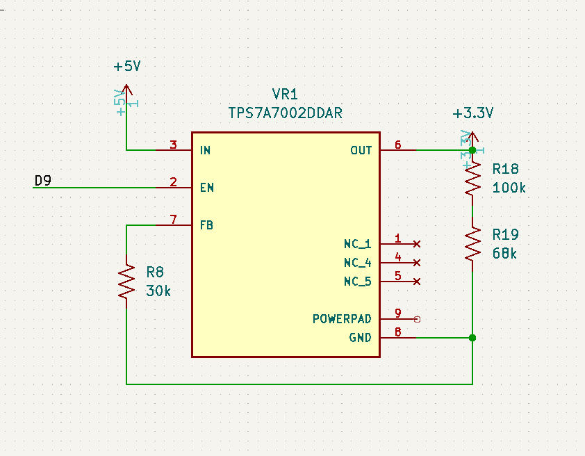
Your schematic is wrong, you are mixed up FB and GND pins of the regulator.
See the picture from datasheet

FB should be connect to the point BETWEEN R1 and R2
Sometimes I wonder why I bother with this hobby - don't seem to be able to get anything right.

Is this better?
Much... ![]()
![]()
![]()
Might be worth putting a 0.1uF cap in FB do to high impedance voltage divider.
Or make Cout as close to the output pin of the regulator as possible.
What do you mean?
Where is Cout? And how do I move it? And how do I put something inside the chip?

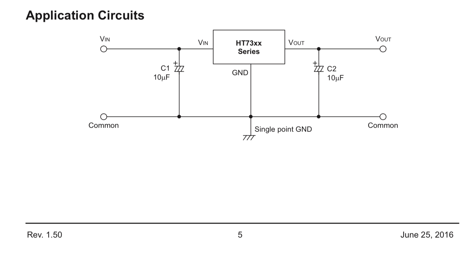
Check out and see if there are any application notes for that regulator.
Tom... ![]()
![]()
![]()
![]()


It is powering a LED and a SD card reader module.
Okay, that will not work.
OP said that he needs ENable pin. This regulator doesn't have it
Unless I powered it off a digital pin on my Uno.
Yes, I just saw that. ![]()
It does have ultra low quiescent current: 3.5μA (typ.)
![]()
1 Like