Stuck in my camera shutter project πŸ˜Άβ€πŸŒ«οΈ

Hey guys,

First, I'd like to say Hello to everyone :v:

I have a camera built myself some years ago. It used a mechanic shutter, completely manual.

Few months ago, I had an Arduino with a Nextion display left from an old unborn project.

Now I'm trying to find a developer to get me some code ready.

The second of these developers got stuck, again. I can't reach to the genius from my last project...so I'm here asking for help or any insights :sweat_smile:

I'll attach four ZIPs here (I'm not allowed to attach, so I'll try with wetransfer)

reqs.zip - that's what I have sent to the developers
first-try.zip - that's what I got back from the first developer
second-try.zip - that's from the second developer (guess it's better than the first)
test.zip - that's a package based on test code from @PerryBebbington and it's working just perfect!

When running the stuff from the first-try.zip or second-try.zip, the Nextion display turns on and is not reacting to input via buttons (they just change colors while pressed).

Can anyone give the final kick to get that stuff working?

Thanks a million in advance!

Welcome to the forum

To post images etc. you need trust level 1, you can get there by:

  • Entering at least 5 topics
  • Reading at least 30 posts
  • Spend a total of 10 minutes reading posts

Users at trust level 1 can...

  • Use all core Discourse functions; all new user restrictions are removed
  • Send PMs
  • Upload images and attachments

From your documentation:


Apart from being sketched awkwardly, this is wired wrong (I'm not aiming at the inappropriately selected 10k base resistor).
The DC converter should be kept powered on, since the power-up time of the converter will likely present a (major) problem especially with shutter speeds below half a second or so, depending on the DC converter used.

Then use some kind of microcontroller-controlled switch to engage the shutter solenoid. A low-side switch would be OK. It's more sensible to use a logic level MOSFET to do this than to have that relay kicking around. This MOSFET will replace the relay + the BC547, although you could keep the BC547 as a poor man's gate driver if you don't want to/can't find a logic level MOSFET.

So what's the problem?

Also, where can the courageous soul willing to give the 'final kick' send their invoice to?

PS: to help out, here's some of the info from your 'reqs.zip' for those unwilling (plausibly) to download random .zips from a random stranger on the internet:


Shutter Control
Nextion:

2 Buttons – β€œ+” and β€œβ€“β€œ to increase or decrease time setting
1 field – showing the time set
1 field – showing the time (duration), how long button2 was pressed

Button 1:

  • Activating the relay on pin A5 for the time chosen via Nextion

Button 2:

  • Activating the relay for as long as the button is pressed

Times to choose from / to scroll through:

Display ms s
1/60 16,67 0,01667
1/30 33,33 0,03333
1/15 66,67 0,06667
1/8 125 0,125
1/4 250 0,25
1/2 500 0,5
1 1000 1
2 2
3 3
4 4
… …
118 118
119 119
120 120

PPS: you should really include a schematic and clear description of all of the hardware. It looks to be more than an Arduino, a DC-DC converter, a shutter solenoid and a Nextion unit.

PPPS: it seems fairly obvious to me that "attempt 1" was generated by/with help of ChatGPT; it's no surprise it doesn't work.

PPPPS: I'd not blame the person who did 'attempt 2' for failing given the dubious project specification they were handed. Although they could be held responsible for not outright turning down the task, as realistically they should have done in the face of guaranteed failure.

1 Like

Thanks for your reply @rsmls

I see, my skills are not good enough...thanks for the advice!

I thought I can overcome the relay lag with some fine adjustments in the end.

You didn't even try to answer the question why the Nextion display is not responding to input from the Arduino board, though.

If you think you can solve that mystery with some awesomeness, then I'm absolutely willing to pay $50, that's not the problem here :wink:

P.S.: There's not more than described:

-Nextion NX8048K050_11
-Arduino Uno
-2x DC-DC converters
-2x hardware buttons
-solenoid switch
-relay assembly

The other parts on the picture are the BMS + some fancy connection assistents...

P.P.S.: Given the small list of parts and the few requirements, I thought this is gonna be easy as pie for a good dev

$50, you are out of touch with the real world. My rate is $250 per hour with a minimum of 3 months.

1 Like

I don't see test.zip
I thought maybe relay_camera_control might be the one you meant, but the HMI configuration doesn't contain anything like my way of doing Nextion and the code uses the official Nextion library, so not mine again.

I've not looked at your other files.

Please follow the instructions from @UKHeliBob in reply #2 and upload to here. You can upload zip files.

To add to what @rsmls said, you have 2 ill defined delays in the wiring: The time it takes the relay to operate and the time it takes the DC/DC converter to start up and then switch off, both together will wreck any attempt at precise shutter speeds. You won't be able to code around these. The best way is a MOSFET as others have said.

I doubt they can, what you are asking assumes that the code is basically correct with a few minor tweeks needed to get it right. I doubt that's the case. More likely (I've not looked beyond the non-existent test.zip) someone would have to start again.

My understanding of your requirements are:

Nextion with:

  • 2 buttons to select from a per-defined list of shutter times
  • Button to trigger the shutter from the selected time
  • Button to trigger the shutter for the duration the button is held down

(You have not specified a precision for the opening times of the shutter)

You also want a circuit that will work.

All to run on an Arduino Uno

Have I missed anything?

Thanks @PerryBebbington !

To be honest, my business was running fine for about a decade, then COVID came and made it hard...now AI ripped the rest out of it.

I have to rethink and a find a "new thing" anyways, maybe it's code.

I'll start my new career today!

The solenoid switch is an electromagnetic switch, that needs at least 21V to trigger the shutter. It just gets voltage from me and was bought as a whole thing...I don't know if it has any diodes.

You see, my electronic skills are as good as my coding skills :rofl:

I'll start with Arduino and Nextion, from your resources and examples.

In a few days there will be more input from me...

Thanks @PerryBebbington for the constructive feedback!

There should be a timer on the Nextion for how long button 2 was pressed...but it seems that's a minor difference from what I've started.

Attached comes the test.zip (Despite the three files in it the official lib is used)
test.zip (180,9 KB)

Can you recommend a good MOSFET switch for my case?

Thanks to all your time and effort in helping here! It's just my hobby and paying a $250 per hour developer is out of my reach :see_no_evil:

I'll get the MOSFET you recommend and then will try to learn some more myself and get someone to help me...just hope that works out


  • As always, show us a good schematic of your proposed circuit. Hand drawn schematics are acceptable.

  • Schematic diagrams are the universal language of electronics

  • We use schematics to communicate hardware design.

  • Show us several good image views of your actual wiring.

  • Give WEB links to your major components.

  • In the Arduino IDE, use Ctrl T or CMD T to format your code then copy the complete sketch.
    Use the < CODE / > icon from the β€˜posting menu’ to attach the copied sketch.

OK, so, 'test' is just my code, which works but doesn't do what you want (it's not meant to).

This is where I am with your project:
I don't see any serious attempt by you to learn to write code on an Arduino or to learn to use a Nextion display, sorry if that's harsh but that's how I see it. The attempts you have made have really been done by others, who have let you down with code and a design that doesn't do what you want. As a rule I don't write code for people, but I do encourage others to write their own code. Only you know why you've not tried to do this yourself. I could write this, but I don't want to, I have more stuff of my own to do that's not getting done, and I have a lot to do at work, and payment doesn't attract me to write code.

As I see it you have 3 options:

  1. Make a clear offer with payment for someone else to do this for you
  2. Make a decent effort to do this yourself
  3. Hope that someone else comes along and decides to do it for you for free

What I think

  1. Does not interest me, but if this is what you want I can move this topic to the paid category of the forum
  2. If I see what I think is a decent effort then when you get stuck I'll probably help, conditional on you using my methods with the Nextion display, not someone else's methods or the ITEAD official library
  3. Good luck, sometimes it happens, sometimes not

Whatever you choose you need a decent project specification.

I'm not sure about a MOSFET but it must be logic level, maybe IRL540 as a starting point. I see an additional problem that I'd not considered. I know little about cameras but I guess the shutter control is a solenoid, solenoids need kickback diodes, kickback diodes slow the release of the solenoid and mess up your timings. This would require experimentation to deal with, unless someone knows the solution (I don't).

Think about what you want, make it clear to everyone.

2 Likes

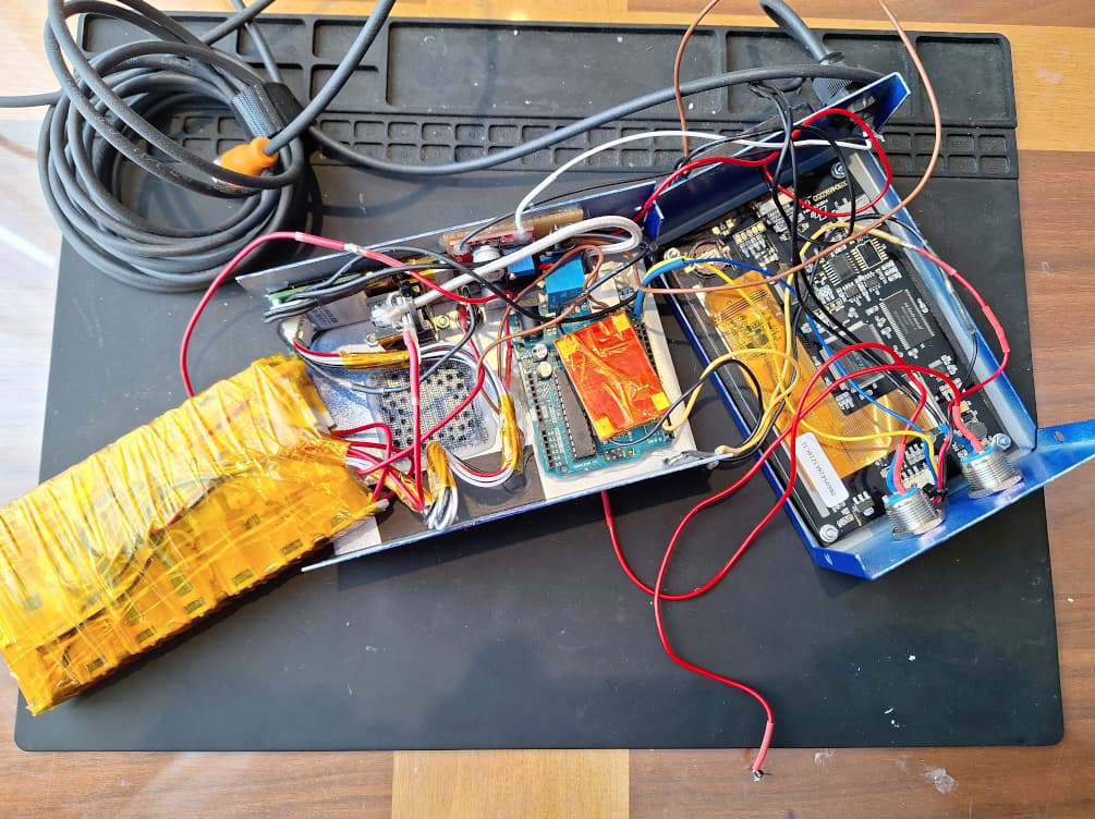
The relay is a complication I'd really just get rid of. It eats power for no really good reason.
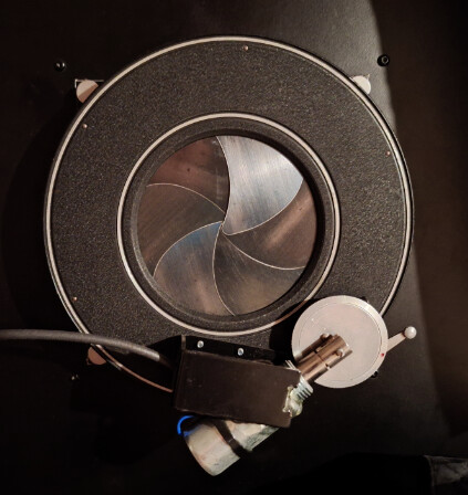
The relay is also not the main source of any lag. These sources are (1) the startup behavior of the DC-DC converter and (2) the inherent inertia of the solenoid itself. (1) is easily solved by connecting things in a smarter way. (2) you could overcome or compensate for in other ways, at least to an extent. Here, it depends mostly on how accurate and consistent you need this thing to be.

No, I frankly see a fairly low-effort attempt at "here is my problem, now you get to solve my sh*t". My response might/would have been different if your question had been "guys, I'm stuck with producing code; I asked a couple of people to help me but that didn't work, I'm now trying to do this myself, but there's a couple of things i don't understand". The latter approach generally works well on this forum. The former tends to be viewed...ah...critically.

That's very generous of you. However, I'm not in it for the money (and it would realistically be an order of magnitude this amount if we're talking about a commercially viable rate).
You'll find that the most valuable help (and even providing some examples) will be done for absolutely free if it's clear that you are willing and able to put in some effort yourself.

OK, let's see it all in one schematic, please.

It depends on the requirements that are not on paper. How accurate and consistent do the timings need to be? Getting this right is pretty much impossible without integrating software and hardware development. If "hey, the thing opens and closes and it sounds pretty close" is good enough, then yes, indeed, it's pretty straightforward and it would actually be a nice project for you to get your feet wet in software development. (hint).

Sorry to have come off a little gruff with you; I respect that this is your hobby, but you see, the same is true for the most of us helping you. That's why it works better if you try to do this yourself and then you get to ask all the questions about the stuff that you don't understand or can get to work, and all of us are going to do our very best trying to help you.

You've stuck around so far and have provided some additional info already, which makes me optimistic about how this might proceed, so I genuinely hope you're willing to install Arduino IDE, practice with getting an LED to blink and then take it from there until you get your shutter to work.

PS: sorry to hear about your business. I hope you can find a new line of work/venture to fill the void.

Greetings from a fellow photographer who's familiar with leaf shutters.

PPS: you may find this helpful: Build a shutter tester for Focal Plane shutters - Cheap, Easy & it Works | Photrio.com Photography Forums

1 Like

Glad to see you're not the grumpy forum troll :rofl:

My first intention was to hire a freelance developer to get that easy thing done...I'm always willing to learn and grow. I just calculated in time: hiring and let someone do would cost less time than learning myself.

Now it seems more likely I'll go the long way, even if I don't need my skills after that again. Maybe it'll be the start of a new business, who knows.

For a photo fellow:

The shutter is for a DIY 30x40cm camera, shooting mostly slow plates in the range of ISO 5. The shutter timings have a generous tolerance of +/- 20% in that case.

I mix all my chemicals from scratch, make my own emulsion and hand-coat my plates. They are then developed as direct positives.

I've spent hours, weeks, months and years to learn all that and get it to the point where I can use it. I'm pretty sure I can learn that coding thing, too :laughing:

1 Like

I've built a tester derived from the PhotoPlug project. A light sensor is hooked to the microphone input of a PC and then the times are checked with Audacity.

A rudimentary, yet reliable setup!

Would it be a solution to use the relay behind the converter, instead of before?

My concern was that the converter uses too much power from my battery in idle, so the relay was hooked before it. At the sacrifice of some accuracy

As a long time photographer who used to have a darkroom I am impressed at your process.
Coding is like learning to play a musical instrument, my sister and I both went to the Royal Conservancy of music up to grade 8. When she plays it sounds like a bad robot, whereas I make music. Same for coding, when I worked at IBM there were programmers there who produced the same garbage day in and day out. They were unteachable because you have to be born with the ability. I have no idea if you have it, but at IBM working 40 hrs a week 50 weeks a year it took two years to get from trainee to associate and many/most retired with no further promotions. People who come on here and say they will just learn coding in a few weeks or months in their spare time make me see red. Given your project, normally I would love to help and in fact would be quite eager, but your attitude has ruined that possibility. Good luck.

I wasn't aware that it requires so much time to learn enough coding for my project.

As I sad before, I thought it's easy, given my little scope of work...

Compared to photography:

#Buying a roll of 135 bw film, shoot at box ISO and develop with a known product doesn't require years of learning.

-> Learning how to code what I need should be possible within months, I guess.

#Mix your own collodio-gelatine emulsion, coat a 30x40cm plate, shoot with feeling and develop to a direct positive needs more than just a few months of fooling around.

-> Learning to code enough to make a living out of it...should take a decent time, but I don't know how long.

Maybe you got me wrong. When I can learn enough to get my project working, this could be the start of a new era, maybe.

Anyways, thanks for your input and bringing me down to earth.

1 Like

BTW:

Can you share a good (the correct) value for it, please?

We take turns.

Yes, putting the switch behind the DC-DC converter will be better.
If you want to make the battery last, consider this:

  • Use a mechanical on/off switch to power down the device when not in use.
  • Forget about the power hungry Nextion display. Use a simple 1620 LCD display with I2C backpack instead.
  • Drop the relay in exchange for a MOSFET.

Coding the project will be fairly easy especially if you ditch the Nextion in favor of a simple I2C display.

Nice job on the emulsion making etc. I know what boat you're in.

1 Like

Try something like 1k or so.

Better yet, forget about it and use a single MOSFET to switch the shutter solenoid. Google "MOSFET low side switch". IRLZ44 is a popular TO220 logic level MOSFET for projects like yours.

1 Like