yes i am on breadboard using LED to test my Logic but by looking at the program everything looks according to logic but on breadboard output is not right at all.
Logic looks odd to me. If you see LOW on the low sensor you turn on the pump. LOW on the high sensor turns it off. What does that do for you if the reservoir is entirely empty? I'd guess that the low water sensor reading will be HIGH, so the pump isn't turned on.
If the water level is lower than the float switch, is the switch OPEN (OFF) or CLOSED (ON)?
Your code appears to be one of each.
here i am using D1 and D2 input_pullup D1 high D2 high means tank is completely empty here case no.1 when pump suppose to start
if water is lower then the sensor then float will return high value
So the switches are normally OPEN, the pullup resistor makes the input HIGH. When water rises and closes the switch, it pulls the input LOW.
If both floats are low, pump should start and stay on even if the bottom switch goes LOW, until the top switch goes LOW. That is not how I read your code.
#include <ESP8266WiFi.h>

// Digital input pin definitions
const int D1_PIN = D1;
const int D2_PIN = D2;
const int D6_PIN = D6;

// Digital output pin definitions
const int D3_PIN = D3;
const int D4_PIN = D4;

// Relay activation durations (in milliseconds)
const int D3_ON_DURATION = 2000;  // 2 seconds
const int D4_ON_DURATION = 1000;  // 1 second

void setup() {
  Serial.begin(115200);

  // Set D1 and D2 as input pins with internal pull-up resistors
  pinMode(D1_PIN, INPUT_PULLUP);
  pinMode(D2_PIN, INPUT_PULLUP);

  // Set D3 and D4 as output pins
  pinMode(D3_PIN, OUTPUT);
  pinMode(D4_PIN, OUTPUT);

  // Set D6 as input pin
  pinMode(D6_PIN, INPUT);

  // Initialize D3 and D4 as low initially
  digitalWrite(D3_PIN, LOW);
  digitalWrite(D4_PIN, LOW);
}

void loop() {
  // Read the input status of D1, D2, and D6
  int d1Status = digitalRead(D1_PIN);
  int d2Status = digitalRead(D2_PIN);
  int d6Status = digitalRead(D6_PIN);

  // Print the status of D1, D2, D3, D4, and D6 on the serial monitor
  Serial.print("D1: ");
  Serial.print(d1Status);
  Serial.print(" | D2: ");
  Serial.print(d2Status);
  Serial.print(" | D3: ");
  Serial.print(digitalRead(D3_PIN));
  Serial.print(" | D4: ");
  Serial.print(digitalRead(D4_PIN));
  Serial.print(" | D6: ");
  Serial.println(d6Status);

  // Check the truth table conditions and perform the corresponding actions

  if (d1Status == HIGH && d2Status == HIGH && d6Status == HIGH) {
    digitalWrite(D3_PIN, HIGH);    // Turn on D3
    delay(D3_ON_DURATION);         // Wait for 2 seconds
    digitalWrite(D3_PIN, LOW);     // Turn off D3
    digitalWrite(D4_PIN, LOW);     // Keep D4 low
  } else if (d1Status == LOW && d2Status == HIGH && d6Status == HIGH) {
    digitalWrite(D3_PIN, LOW);     // Turn off D3
    digitalWrite(D4_PIN, LOW);     // Keep D4 low
  } else if (d1Status == LOW && d2Status == LOW && d6Status == HIGH) {
    digitalWrite(D3_PIN, LOW);     // Turn off D3
    digitalWrite(D4_PIN, HIGH);    // Turn on D4
    delay(D4_ON_DURATION);         // Wait for 1 second
    digitalWrite(D4_PIN, LOW);     // Turn off D4
  } else if (d6Status == LOW) {
    digitalWrite(D3_PIN, HIGH);    // Turn on D3
    delay(D3_ON_DURATION);         // Wait for 2 seconds
    digitalWrite(D3_PIN, LOW);     // Turn off D3
  }

  // Add a delay to prevent continuous checking
  delay(1000);
}
please go through my code even this is not working as given truth table
You may get some idea from the following Arduino UNO based two pump system.
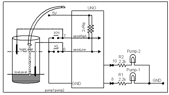
Figure-1:
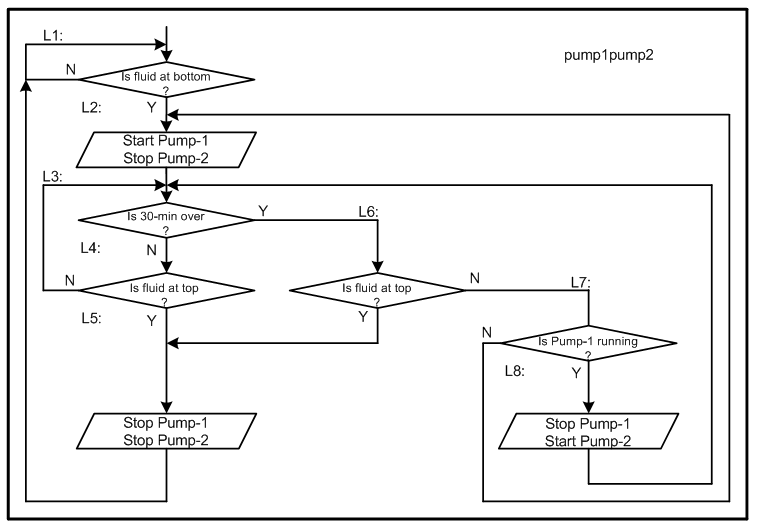
Figure-2:
Algorithm:
(1) When fluid level is at Bottom (equivalent to closing button KL switch), Pump-1 will start.
(2) When fluid level is at Top (equivalent to closing button KH) Pump-1 stops.
(3) When fluid level is at Top and Pump-1 has run for 30-min, Pump-1 stops.
(4) When fluid level is not at Top but Pump-1 has run for 30-min, Pump-1 stops and Pump-2 starts.
(5) When fluid level is at Top (equivalent to closing button KH) Pump-2 stops.
(6) When fluid level is at Top and Pump-2 has run for 30-min, Pump-2 stops.
(7) When fluid level is not at Top but Pump-2 has run for 30-min, Pump-2 stops and Pump-1 starts.
(8) Goto Step-2.
Sketch-1: The following sketch prepared using goto statement for easy understanding and quick development of the program. In programming, the use of goto statement is highly discouraged. In Sketch-2, the goto statement is removed. In Sketch-1, the time delay is 8-sec (for test purpose) and it has been created using TC1 of the MCU. The program senses the end of time delay on interrupt basis.
#define sensLow 6
#define sensHigh 7
#define Pump1 8
#define Pump2 10
bool p1On = false;
bool p2On = false;

volatile bool runTimeIsOver = false;
volatile int irqCounter = 0;

void setup()
{
  pinMode(8, OUTPUT);
  pinMode(10, OUTPUT);
  pinMode(sensLow, INPUT_PULLUP);
  pinMode(sensHigh, INPUT_PULLUP);
  //-------------------------------
  TCCR1A = 0x00;
  TCCR1B = 0x00;
  TCNT1 = 3036;  //for 4-sec time dealt with 1024 prescaler
  TCCR1B = 0x05;
  bitSet(TIMSK1, TOIE1);
}

void loop()
{
L1: if (digitalRead(sensLow) == LOW)
  {

L2: digitalWrite(Pump1, HIGH);
    p1On = true;
    digitalWrite(Pump2, LOW);
    p2On = false;

L3: if (runTimeIsOver == true)
    {
      runTimeIsOver = false;
      goto L6;
    }

L4: if (digitalRead(sensHigh) == HIGH)
    {
      goto L3;
    }

L5: digitalWrite(Pump1, LOW);
    p1On = false;
    digitalWrite(Pump2, LOW);
    p2On = false;
    goto L1;

L6: if (digitalRead(sensHigh) == LOW)
    {
      goto L5;
    }

L7: if (p1On == false)
    {
      goto L2;
    }
L8: digitalWrite(Pump1, LOW);
    p1On = false;
    digitalWrite(Pump2, HIGH);
    p2On = true;
    goto L3;
  }
}

ISR(TIMER1_OVF_vect)
{
  TCNT1 = 3036;  //4-sec time delay parameter at prescaler 1024
  irqCounter++;
  if (irqCounter == 2)//8-sec delay
  {
    runTimeIsOver = true;
    irqCounter = 0;
  }
}
Sketch-2:
Converting Flow Chart of Fig-2 into Control Codes/Sketch without goto statement and using millis() function for time delay.
#define sensLow 6
#define sensHigh 7
#define Pump1 8
#define Pump2 10
unsigned long prMillis = 0;
bool pump1State = LOW;
bool pump2State = LOW;

void setup()
{
  pinMode(8, OUTPUT);
  pinMode(10, OUTPUT);
  pinMode(sensLow, INPUT_PULLUP);
  pinMode(sensHigh, INPUT_PULLUP);
  while (digitalRead(sensLow) != LOW)
  {
    ;  //wait until fluidLevel falls at Bottom
  }
  pump1State = !pump1State;
  digitalWrite(Pump1, pump1State); //on
}

void loop()
{
  prMillis = millis();
  while (millis() - prMillis < 5000ul)  //5-sec test interval
  {
    if (digitalRead(sensHigh) == LOW)
    {
      digitalWrite(Pump1, LOW); //on
      digitalWrite(Pump2, LOW); //on
      while(digitalRead(sensLow) != LOW)
      {
        ;   //wait  until fluidLevel falls at Bottom
      }
      break; //turn on the next Pump in sequence
    }
  }
  pump1State = !pump1State;
  digitalWrite(Pump1, pump1State); //on-off
  pump2State = !pump2State;
  digitalWrite(Pump2, pump2State); //on-off
}
Here's a basic 1 second ON delay, trigger could be a button press (debounced) or a pulse from a code function.
Pseudocode
if(not timing and trigger)
{
  timer = millis();
  timing = true;
}
if(millis() - timer > 1000)
{
  timing = false;
}
outPin = trigger or timing;
1 Like
This topic was automatically closed 180 days after the last reply. New replies are no longer allowed.