hi i am planning to code Submersible pump starter with water level controller using Node MCU i wanted to use float type level switches for detection of water level i tried to make the code but desired output is not coming.
- as soon as water goes below low level (D1 pin goes low) pump start relay must be on for 2 second to start the pump and after that remains stop.
- as soon as water level goes above high level ( D2 pin goes low) pump stop relay must activate for 1 second to stop the pump.
- there must be auto manual switch (D6) input for running pump irrespective of water level. but manual switch must also follow same start and stop procedure.
please help
1 Like
Hello aamiragwani
We need some additional information.
Post your sketch, well formated, with well-tempered comments and in so called code tags "< code >" and a detailed circuit diagram to see how we can help.
Have a nice day and enjoy coding in C++.
// Pin assignments
const int lowLevelFloatSwitchPin = D1;      // GPIO pin for low level float switch
const int highLevelFloatSwitchPin = D2;     // GPIO pin for high level float switch
const int pumpStartRelayPin = D3;           // GPIO pin for pump start relay
const int pumpStopRelayPin = D4;            // GPIO pin for pump stop relay
const int autoManualSwitchPin = D6;         // GPIO pin for auto/manual switch

// Timings (in milliseconds)
const unsigned long pumpStartDelay = 2000;  // Delay to keep pump relay active after low level detected
const unsigned long pumpStopDuration = 1000;   // Duration to activate stop relay after high level detected

// Variables
bool isPumpRunning = false;                  // Flag to track the pump state
unsigned long pumpStartTime = 0;             // Timestamp to track pump start delay
bool isStopRelayActive = false;              // Flag to track the state of the stop relay
unsigned long stopRelayActivationTime = 0;   // Timestamp to track stop relay activation time

void setup() {
  Serial.begin(9600);                       // Initialize serial communication
  pinMode(lowLevelFloatSwitchPin, INPUT_PULLUP);   // Set low level float switch pin as input with internal pull-up resistor
  pinMode(highLevelFloatSwitchPin, INPUT_PULLUP);  // Set high level float switch pin as input with internal pull-up resistor
  pinMode(autoManualSwitchPin, INPUT_PULLUP);      // Set auto/manual switch pin as input with internal pull-up resistor
  pinMode(pumpStartRelayPin, OUTPUT);               // Set pump start relay pin as output
  pinMode(pumpStopRelayPin, OUTPUT);                // Set pump stop relay pin as output

  // Initial state
  digitalWrite(pumpStartRelayPin, LOW);
  digitalWrite(pumpStopRelayPin, LOW);
}

void loop() {
  // Check the auto/manual switch
  bool isAutoMode = digitalRead(autoManualSwitchPin) == HIGH;

  // Check the low level float switch
  if (digitalRead(lowLevelFloatSwitchPin) == LOW && isAutoMode) {
    if (!isPumpRunning) {
      // Start the pump
      digitalWrite(pumpStartRelayPin, HIGH);
      isPumpRunning = true;
      pumpStartTime = millis();
    } else if (isPumpRunning && (millis() - pumpStartTime >= pumpStartDelay)) {
      // Deactivate the pump relay after pumpStartDelay
      digitalWrite(pumpStartRelayPin, LOW);
    }
  }

  // Check the high level float switch
  if (digitalRead(highLevelFloatSwitchPin) == LOW && isAutoMode) {
    if (!isStopRelayActive) {
      // Activate the stop relay
      digitalWrite(pumpStopRelayPin, HIGH);
      isStopRelayActive = true;
      stopRelayActivationTime = millis();
    } else if (isStopRelayActive && (millis() - stopRelayActivationTime >= pumpStopDuration)) {
      // Deactivate the stop relay after pumpStopDuration
      digitalWrite(pumpStopRelayPin, LOW);
      isStopRelayActive = false;
    }
  }

  // Print pin statuses to the serial monitor
  Serial.print("D1: ");
  Serial.print(digitalRead(lowLevelFloatSwitchPin));
  Serial.print(" | D2: ");
  Serial.print(digitalRead(highLevelFloatSwitchPin));
  Serial.print(" | D3: ");
  Serial.print(digitalRead(pumpStartRelayPin));
  Serial.print(" | D4: ");
  Serial.print(digitalRead(pumpStopRelayPin));
  Serial.print(" | D6: ");
  Serial.println(digitalRead(autoManualSwitchPin));

  delay(100); // Delay for stability and to reduce serial output rate
}
1 Like
You'll need to provide info on just what is actually working.........the latter part of your quote means nothing to us.
this is the circuit diagram.
1 Like
10:56:22.798 -> D1: 1 | D2: 1 | D3: 0 | D4: 0 | D6: 1
10:56:22.888 -> D1: 1 | D2: 1 | D3: 0 | D4: 0 | D6: 1
10:56:22.981 -> D1: 1 | D2: 1 | D3: 0 | D4: 0 | D6: 1
10:56:23.122 -> D1: 1 | D2: 1 | D3: 0 | D4: 0 | D6: 1
10:56:23.216 -> D1: 1 | D2: 1 | D3: 0 | D4: 0 | D6: 1
10:56:23.310 -> D1: 1 | D2: 1 | D3: 0 | D4: 0 | D6: 1
10:56:23.403 -> D1: 1 | D2: 1 | D3: 0 | D4: 0 | D6: 1
10:56:23.497 -> D1: 1 | D2: 1 | D3: 0 | D4: 0 | D6: 1
this is the output i am getting at serial monitor.
Hi,
Can I make a suggestion, it will make your code easier to read and possibly function better.
You are digitalReading all over your code, it would be easier if you read ALL your inputs at once at the top of the loop(), assign variables, and use those variables through your code.
In other words take a snapshot of your system and then act on it, then the loop repeats.
bool LowLevelFloatStatus = digitalRead(lowLevelFloatSwitchPin);
bool HighLevelFloatStatus = digitalRead(highLevelFloatSwitchPin)
Another thing woud be to have
bool PumpStatus = HIGH;
PumpStatus = LOW;
bool AutoManualStatus
Use those through your code, then at the end of the loop()
Using if.. else statemants for each variable.
Thanks.. Tom.. 


1 Like
for the schematic! Not perfect but hand written and useful!
I guess the relay card power is still missing...
Hi,
You have ;
So your manual switch should be between D6 and ground.
Tom..
this is the what i am getting from my code.... need help
Hi,
I presume that a "1" on the D1 and D2 inputs mean the tank level is above the sensor.
If so when D1 is "0", D2 HAS TO BE "0".
The upper sensor cannot show full if the lower sensor is showing empty.
Re-evaluate your test table procedure.
Tom...
Wondering if you understand the working if you could provide me completely new program satisfying my requirement, debugging is frustrating:(
Well done. Table is clear.
But you need to tell what you expected...
So add a second table that shows what you want. And indicate the differences...
And do the renaming as Tom suggested and post your code again...
Yes debugging is frustrating. But it needs to be done and you will get better at it. And it will prove that it is really worthwhile to spend time on making your program more easy to read (for us but most of all for yourself...).
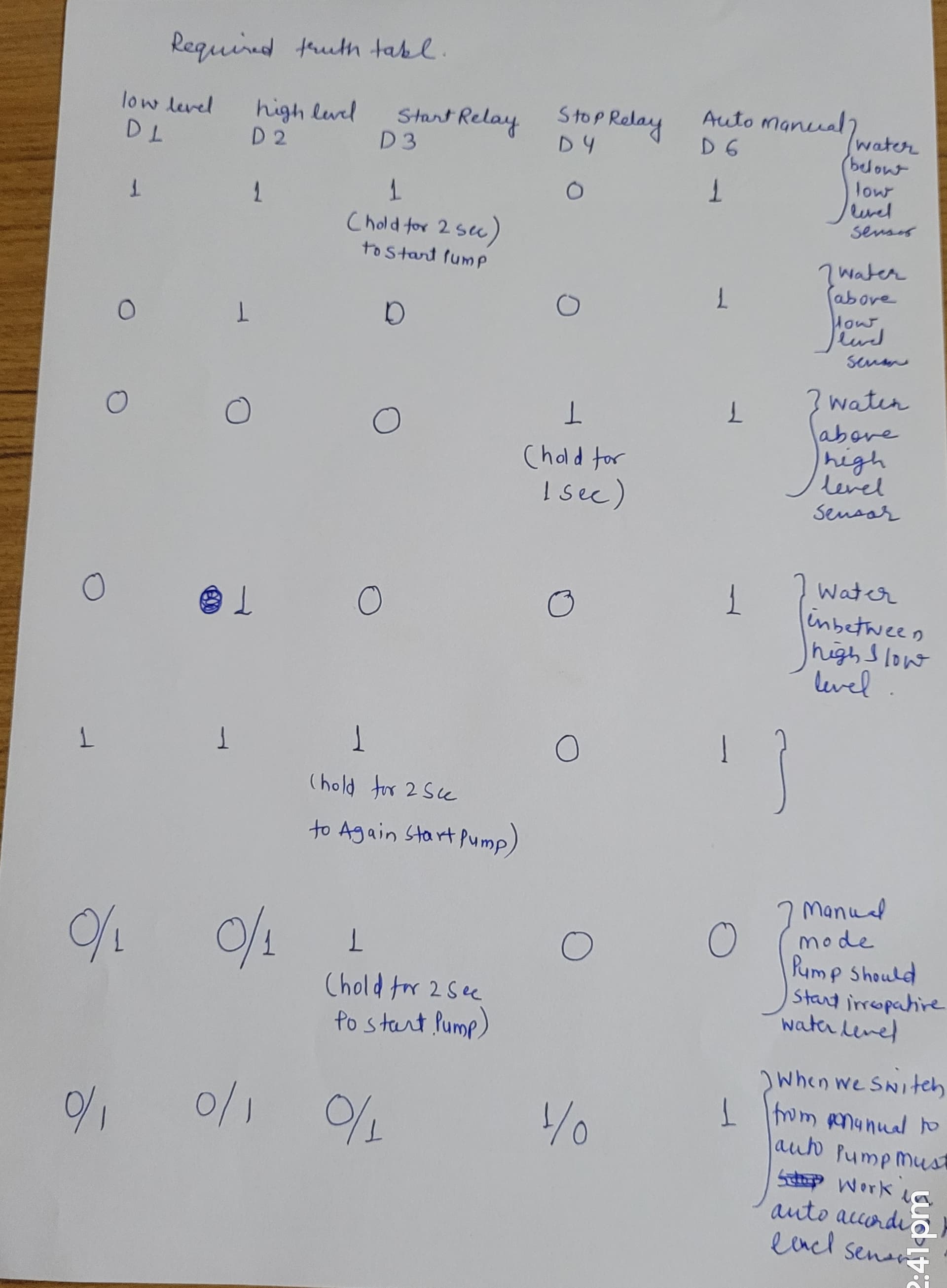
this is the required truth table
And now read and study the IPO model to get proper started.
please help in realizing this code.
Especially if you write the entire program before you start testing.
I'd be inclined to disconnect the pump relays and then run the program with a longer delay and examine what the serial output does as you pour water into the reservoir. Then add some additional prints to tell you what the pump is doing.
I'd forget the complication with the start & stop relays too and just simulate the pump with an LED until you get your logic right.