Hi all
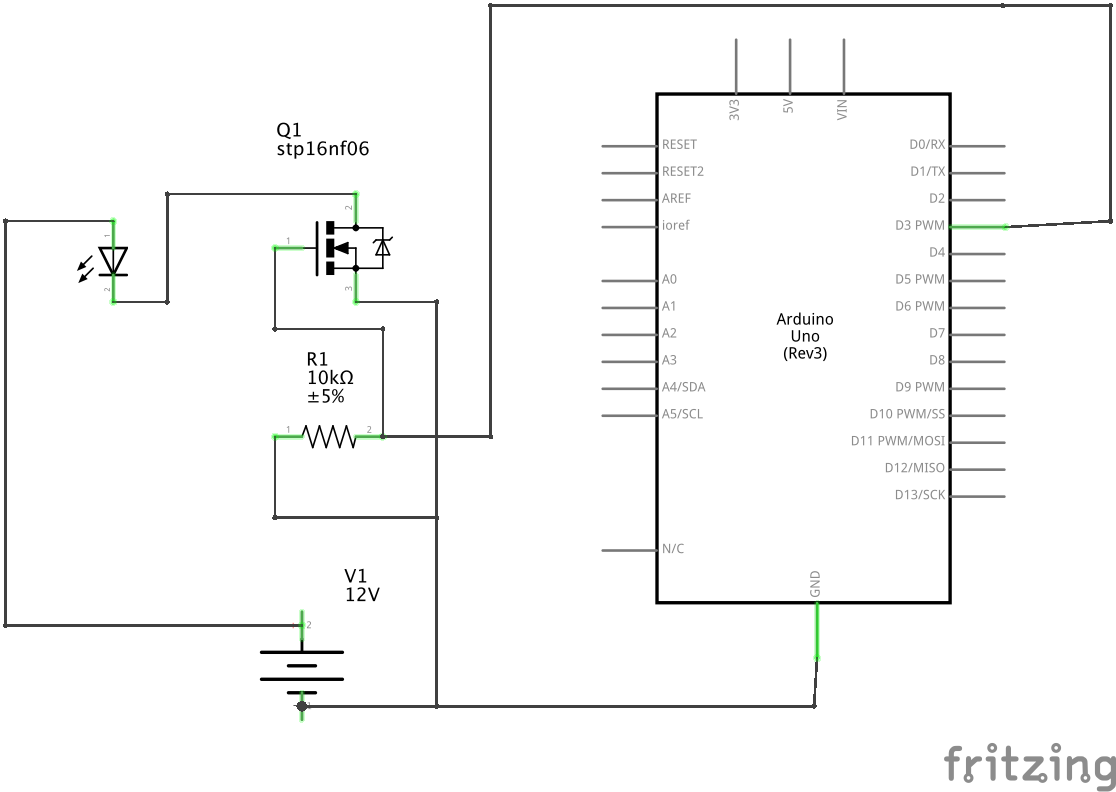
I've attached a proposed schematic.
I need to control a vehicle alarm unit using 12v (shown in the schematic as the LED)
I've chosen a stp16nf06 MOSFET as they are cheap and easy to get where I am
Does this circuit look safe? I believe I don't need a diode if I'm not controlling a coil
Paul__B:
That may be true for a LED, but a vehicle alarm unit is usually connected to the door switches and other parts of the wiring.
Whatever do you mean by "control a vehicle alarm unit"?
A STP16NF06 is not a logic-level FET, so is completely unsuitable for controlling any form of power when controlled by an Arduino.
To explain further, all my door triggers (via the interior light circuit) are connecting to the analog inputs of the arduino. The software eliminates any false alarms etc.
I have an off the shelf car alarm system that has a negative trigger wire. When the signal goes from 12v to ground it sets off the alarm. So basically I need to 'output' 12v from the Arduino
Also be aware that a vehicle electrical system can be electrically noisy , and voltages can go up to 14v or so.
I would take precautions ; for example such as using opto couplers on any input/outputs , and some form of power supply smoothing - eg pre regulate with a 7809 regulator and some capacitors .
rferder:
I have an off the shelf car alarm system that has a negative trigger wire. When the signal goes from 12v to ground it sets off the alarm. So basically I need to 'output' 12v from the Arduino
OK, so it does not sound as if you are actually switching any significant current or power, so that makes it easier.
Of these, the mysterious ZK8821 sounds as if it may well be suitable, but with no identification on the encapsulation and no datasheet, it is difficult to determine.
Paul__B:
OK, so it does not sound as if you are actually switching any significant current or power, so that makes it easier.
Of these, the mysterious ZK8821 sounds as if it may well be suitable, but with no identification on the encapsulation and no datasheet, it is difficult to determine.
I've found this and it appears to be logic level
Does this look suitable?
hammy:
Also be aware that a vehicle electrical system can be electrically noisy , and voltages can go up to 14v or so.
I would take precautions ; for example such as using opto couplers on any input/outputs , and some form of power supply smoothing - eg pre regulate with a 7809 regulator and some capacitors .
I have been using this regulator to supply my Arduino with 12v
Maximum voltage 35 V - should be reasonable adequate. But you should not be powering an Arduino with 12 V - that is not safe. An Arduino runs on 5 V and that regulator should be fine to power it.
I meant to drop in to Jaycar after church to suss out the ZK8821 but forgot. Maybe some other time.
Maximum voltage 35 V - should be reasonable adequate. But you should not be powering an Arduino with 12 V - that is not safe. An Arduino runs on 5 V and that regulator should be fine to power it.
I understood that an Arduino Uno r3 can accept any voltage from 6-20v and that the recommended input was 12v?
rferder:
I understood that an Arduino Uno r3 can accept any voltage from 6-20v and that the recommended input was 12v? https://store.arduino.cc/usa/arduino-uno-rev3
This was the official information I've been working from
Yes, that's a big worry.
The confusion is encouraged by descriptions in the Arduino references that there is an on-board regulator on these boards. This is true - there is a regulator on the board and it can be used under limited circumstances to power the Arduino board and only the Arduino board. Essentially nothing else as the regulator, whatever its rated capacity, has no effective heatsink and will overheat and (hopefully safely) shut down if required to provide more current than the microcontroller itself and a few indicator LEDs at 10 or 20 mA each.
The "Vin" pin or in fact the "barrel jack" which is the same with a diode, was provided to demonstrate the Arduino. Once you start connecting things that draw current, and that includes connecting things to draw current from the "5V" pin, you are playing with fire - or not! This is even worse for the Mega as it has more pins to connect things to!
The on-board regulator - unless you use a variant such as the "RoboRed" (it has a proper switchmode regulator) - has no heatsink of significance. It may theoretically have a rating of 1 A, but only when bonded to a substantial heatsink. You can barely see it on the Arduino board. You will not get 1 A at 5 V from the board with any "Vin" voltage for more than a second or two before the regulator overheats - and hopefully shuts down peacefully. You may be lucky to get 150 mA.
It is thus extremely bad design to use "Vin" in a serious project. Even if it works at a start, any modification may later cause trouble.
The microprocessor and its peripherals operate from 5 V. If you have 5 V then you provide it to the "5V" terminal. You can fudge it by connecting something such as a USB charger to the USB connector but there is a 500 mA polyfuse on the UNO/ Mega and a diode on the Nano interposed. If you do not have 5 V, then you provide a switchmode regulator to produce regulated 5 V.
Wow I'm finding this oversight from the official documentation really shocking! 5v it is, thanks for the heads up
I had the opposite problem When I first bought an Uno 5 or so years back, all I saw was the 5V in all the docs. So I bought a 5V wall-wart for the barrel jack; only when I read further I realised it needed 7V or so.
Still, the wall wart's a nice 2A one so I stick an adapter on the end and now use it foe servos etc.