I am working on a timer project with 3 input buttons.
I have a working prototype for the input buttons on a breadboard and I'm trying to get it onto perf board to free up my breadboard for future projects.
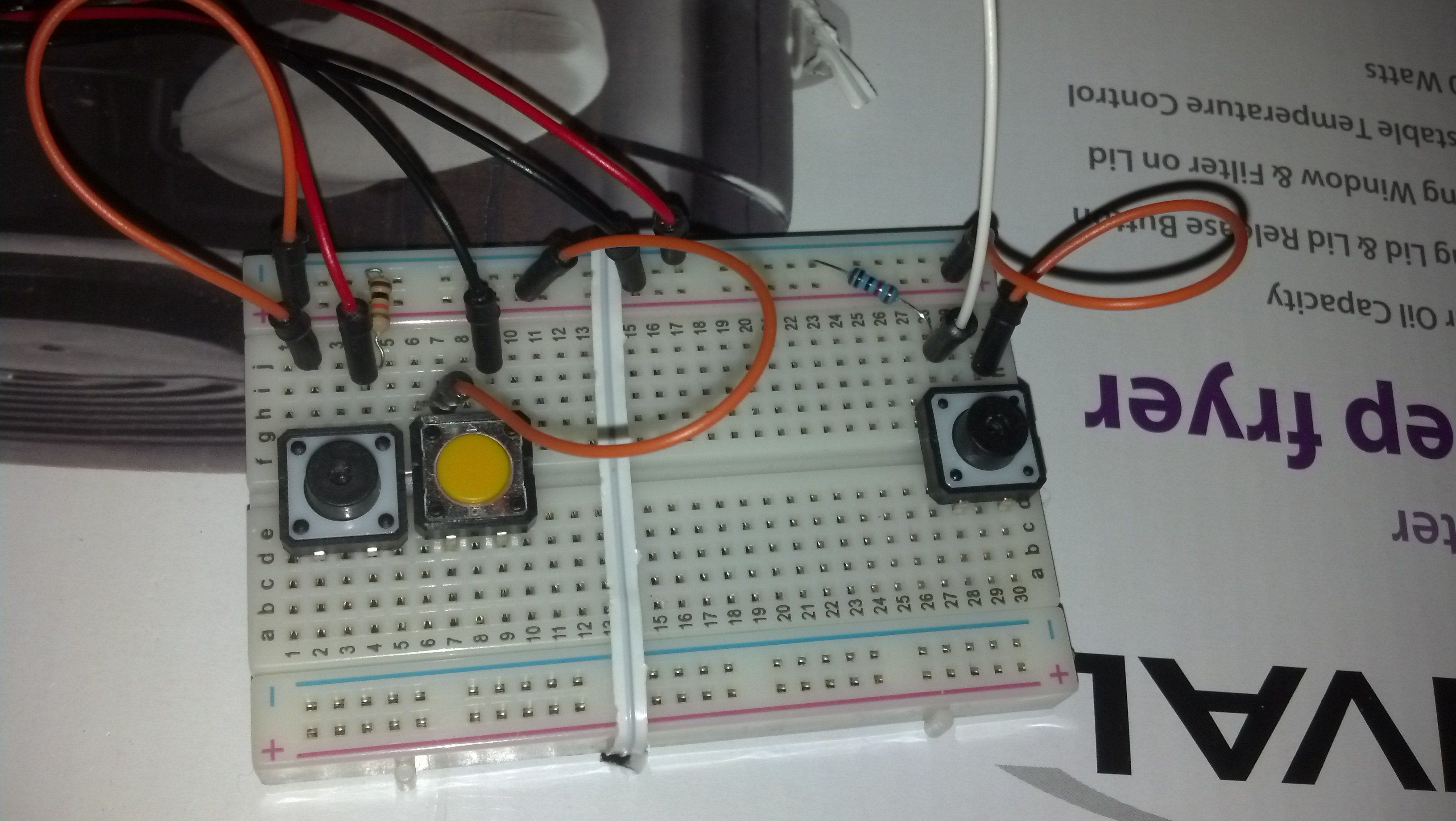
on my bread board i have my positive bus connected to 3.3v ground bus to ground,
from the positive bus i have separate 10Kohm resisters going to each button.
I then have a jumper going from each button(same side as 3.3v are connected to resister in a Pull Up configuration).
I then have the other sides of each switch connected to ground so when the buttons are not pushed they read HIGH and when they are pressed it reads LOW.
when I built my perf board version i built it very similar but i made it with 2 differences.
1)I used a single 10kohm resistor (i did this thinking i could save space on the board)
2)I connected the closed side of each switch to each other in series and then ran a single wire to the ground pin on my header.
Im guessing that not having a separate resister on each button is the cause of my trouble, im not really knowledgeable about electronic components, but i imagine that without the resistor on each switch that each of the buttons will read LOW when one button is pressed
I guess im just looking for confirmation that Im on the right track before I proceed.
I also will attach photos of my breadboard and perfboard.
You don't need external pullup resistors at all.
Pre-setup code:
byte pinX = #; // from 0 to 19 for Uno
In setup:
pinMode (pinX, INPUT_PULLUP);
with button that connects the pin to Gnd when pressed
In usage:
if (digitalRead(pinX) == LOW){
// button was pressed, do something
}
I realize that Pull Down probably isnt the best way to go, but its the way I built it.
< i had terminoligy wrong its pull up. >
Your description is not PullDown; you have external pullup resistors, and buttons that can connect a pin to Gnd when pressed.
ok well perhaps i'm confused on the terminology to me the button being pressed is pulling the signal down from HIGH to LOW. I will admit when i'm wrong.
That being said my breadboard worked, so to me the reason this one doesn't is the resistors.
I believe you are saying my code can be altered so the board reads the input differently and my perfboard design will work?
Yes, terminology error.
I then have the other sides of each switch connected to ground so when the buttons are not pushed they read HIGH and when they are pressed it reads LOW.
That's what I showed in the code description above as well.
Put a meter on the pin you are pressing the button for, confirm its actually being pulled low.
OK. I think I know whats happening.
on the breadboard with separate resistors on each button, when i press button 1 its voltage drops to 0, but at the same time buttons 2 and 3 drop to about 1.5 volts. the same happens with each button so when it is pressed the voltage drops, but not to 0.
on the perfboard, when I press button 1, or 2, or 3, the voltage on all 3 drops to 0. so it is like i am pressing all 3 buttons at once.
i assume that separating out each button with its own resistor is whats preventing the complete voltage drop on unpressed buttons on the breadboard version.
Yes. As I said, you don't need any resistors. 1 button connects to 1 pin, and Gnd.
yeah. i get that for future project. regardless I found it was simple enough to just put a resistor on each button like my breadboard has and worked with. I got it to work so im satisfied.